8$ RC kill switch!
18 March 2015
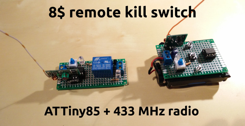
In this article I will cover the basics of a remote controlled kill switch that you can deploy in your house, your embedded project, your autonomous vehicle or anywhere else you see fit! After some months of absence from this blog, during which I was engaged in some very interesting projects [1] [2] I should write about at a point, I am back for this new little gadget I made.
At the University, we were tasked to create an autonomous vehicle that should be able to run around a track, park and overtake obstacles utilizing an on-board camera and various sensors. I thought to facilitate the development and field testing process, by making a kill switch for the vehicle’s motors, in case something goes wrong. We needed a fast and dependency-free way to turn the motors off, in case the image processing unit sends wrong instructions to the micro-controller in charge of the motors or the connection between them is disrupted. Another thing that could go wrong, would be the micro-controller to get stuck in an infinite loop, to deadlock or generally fail somehow. We also knew that many accidents occurred in the past, especially during field testing at high speeds. Moreover, a driver behind the design decisions and the components selection, was affordability. The system had to be cheap and easy to make, using common components.
The above requirements, lead me to begin with a simple radio transmitter with a button. When pressed, it will send a message to a receiver connecting the power source and the electronic speed controller (ESC) of the motors. When the receiver gets the message, it will signal a relay that will turn the voltage to the ESC off. The micro-controller of choice was the ATTiny85 (about which I will organize a workshop in a month), providing everything we need in a small package and a low price-tag (1$). Some LEDs and on/off switches were additionally included in order to increase the usability of the system.
Software-wise, the ATTiny85 sketches use the VirtualWire library in order to utilize the radio modules (1$). More specifically, a button is attached to an interrupt pin on the ATTiny85 which when triggered sends a predefined string through the radio transmitter. When the receiver detects that specific text, sets the base of an NPN transistor to high. The transistor, triggers a relay that opens the connection between the power source and the ESC. The circuit will remain open for safety reasons, until the kill switch is manually reset. There is an on off switch with an indicative LED for that. A 3 AA-battery pack is attached to the transmitter, while the receiver can be powered through a terminal, with up to 5.5 volts. It might be possible to power everything up with 2 AA-batteries, but I did not want to test the system’s limits and range, so I did not try it.
[caption id=”attachment_231” align=”aligncenter” width=”300”]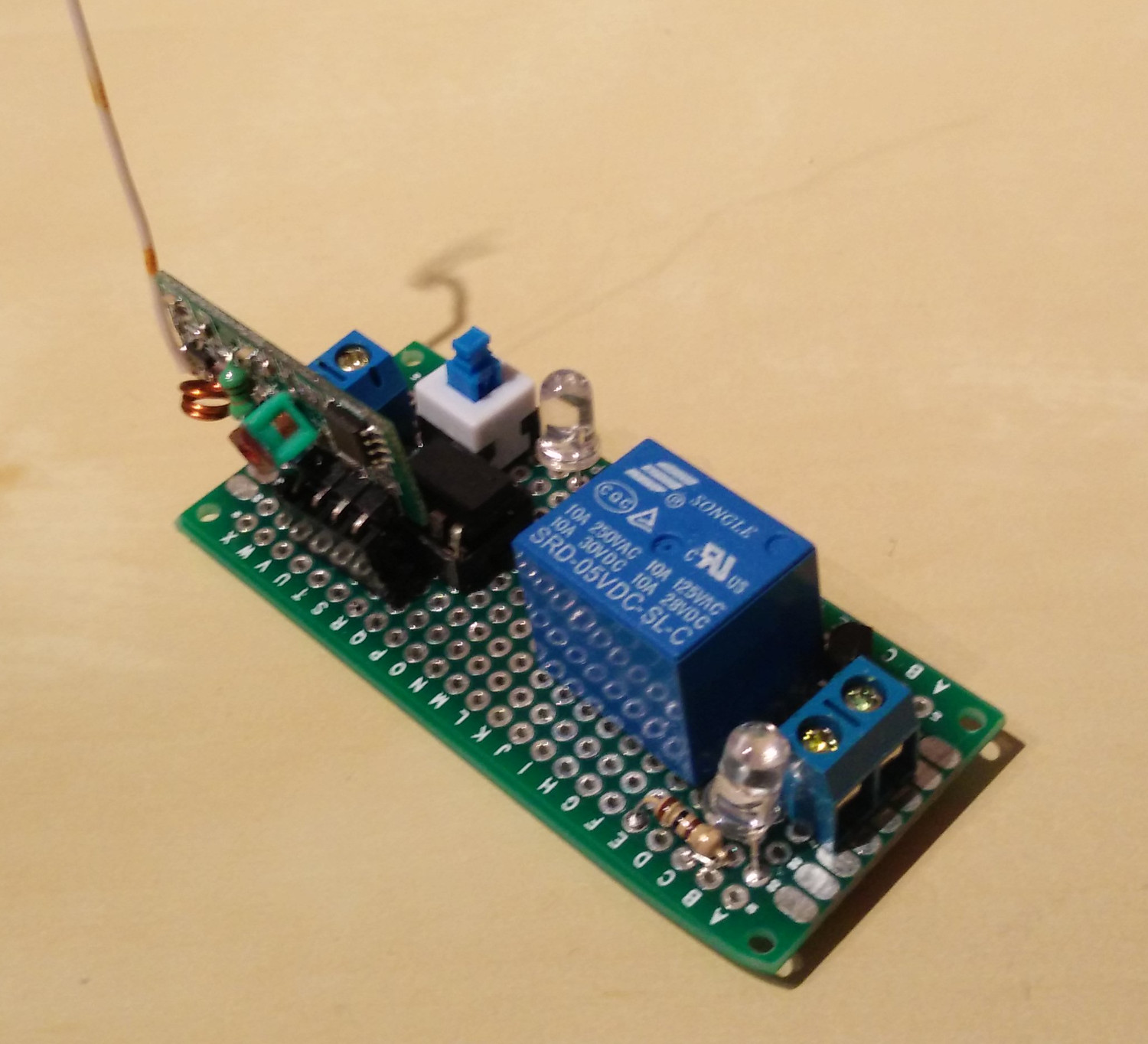 Receiver[/caption]
[caption id=”attachment_230” align=”aligncenter” width=”296”]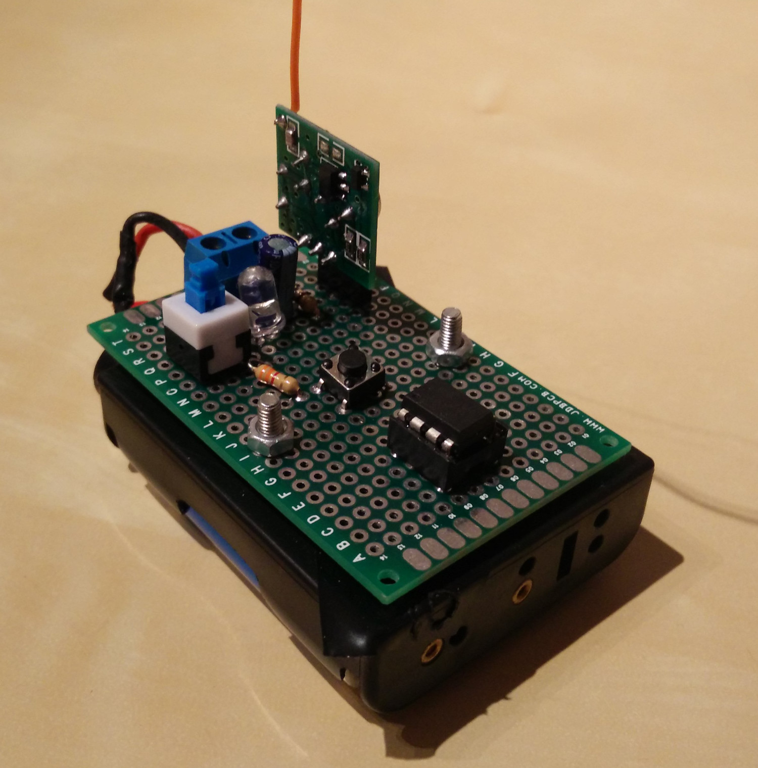 Transmitter[/caption]
The total cost for the system should not exceed the 8$ mark, if everything is ordered from China. Its range is 10-20 meters and has been tested to work even with a wall between them. Furthermore, these inexpensive radio modules are generally a good option for home automation and DIY projects, however they are not reliable enough for a professional or industrial application. Making everything (programming, testing and soldering) from scratch, took me around 7-8 hours, so if your soldering skills are better than mine, you should need much less than that. The ATTiny85’s were programmed using an open hardware Arduino ATTiny programmer shield, that I found here. By the way, I have used the ATTiny85 before, in an Adafruit Trinket, for my Bluetooth controlled spider!
Below you can find the schematics for the receiver and the transmitter. If you need any help, recreating this or making something similar, don’t hesitate to contact me.
[caption id=”attachment_228” align=”aligncenter” width=”300”]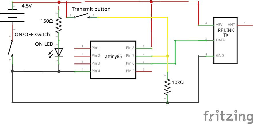 Transmitter[/caption]
[caption id=”attachment_227” align=”aligncenter” width=”300”]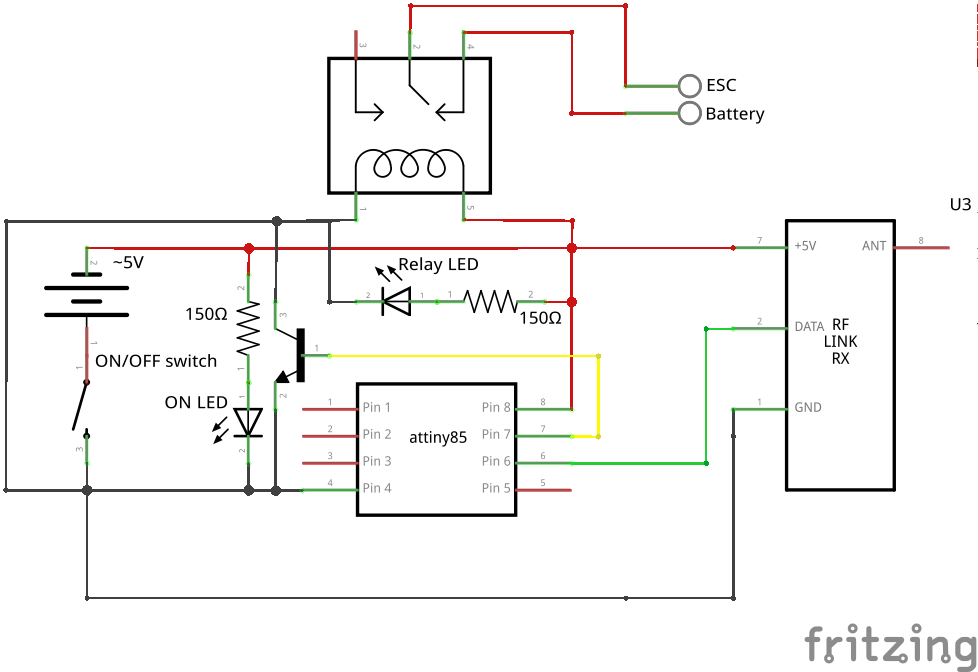 Receiver[/caption]
[caption id=”attachment_232” align=”aligncenter” width=”300”]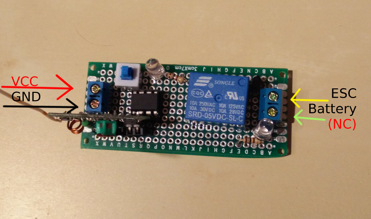 Receiver’s connection schema[/caption]
