A path following vehicle called Alice
02 August 2015
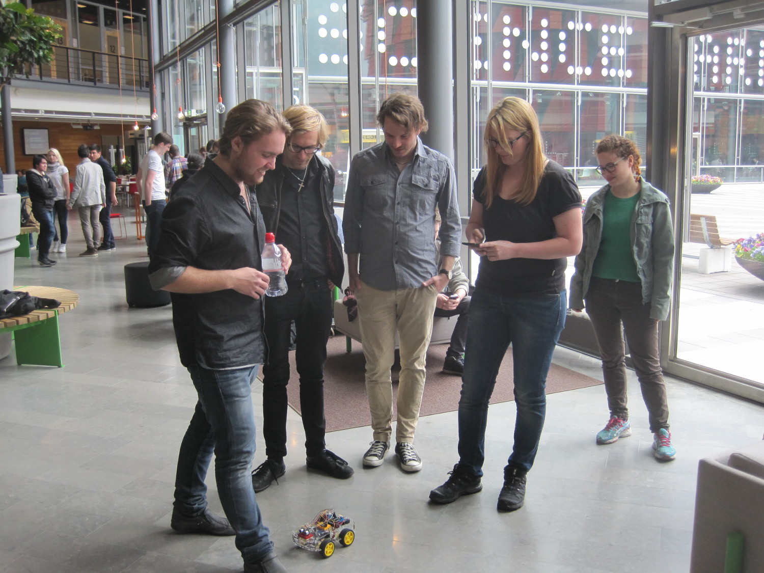
During the last term, my team and I were not the only ones creating a vehicle, controlled by Android. A group of first year students, at the Software Engineering and Management program, of the University of Gothenburg, were also developing one of their own. They created an Android application, which enables them to draw a path on the screen with their finger. This, is interpreted as a set of driving instructions to be sent via Bluetooth to an Arduino based vehicle, that executes them and therefore follows the drawn path. Let’s see how they describe their product.
The system we developed, consists of two components:
1. An autonomous car, programmed on the Arduino platform.
2. An application for a portable “smart” device (a smartphone or a tablet computer), currently running on the android platform. The user draws a path directly on the screen of the portable device for the car to follow. The car and the portable device communicate via Bluetooth. The car is equipped with an obstacle-detecting sensor (currently ultrasound). Should an obstacle be detected, the car stops and the user is presented with two possible choices: either control the car manually, or instruct the car to carry out previously sent instructions if the obstacle is deemed to not be a threat. The user can upload an image (i.e. floor blueprints) to the application and draw the path directly on top of the chosen image. This simplifies the process of drawing a more precise path over a larger area.
The software could be incorporated into alternate hardware for specialized and repetitive tasks, such as moving stock through a factory or warehouse. There is also a potential to use the car for similar tasks in areas and environments which are unsafe for humans.
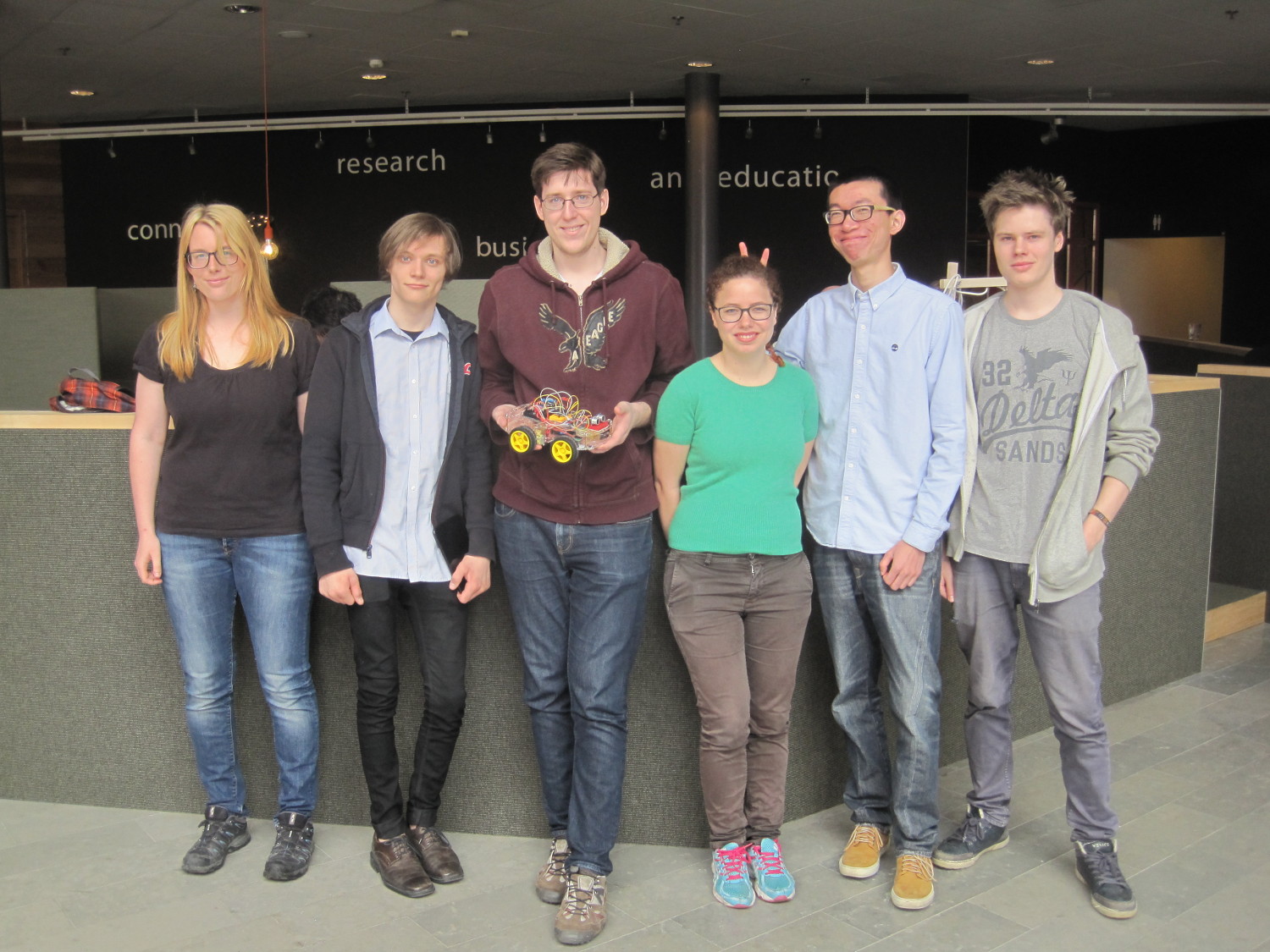
The team behind the path following vehicle, which they code-named “Alice” is: Kai Salmon, Martina Freiholtz, Tobias Lindell, Rachele Mello and Linhang Nie. You will find all the relevant code in their SmartCar GitHub repository. They use the Smartcar Core and the Smartcar Sensors Arduino libraries, which were created for them. They have not published the code under a FOSS license, or any license for that matter, however I believe it is a matter of time (blame it on the summer holidays), before they do. So, let’s get a deeper look into it, but first, check out this video!
In January, I approached the professors of DIT524, which is a group project course about ”Systems development” and proposed two student teams to work on a small vehicular platform that I built, based on Arduino Mega, accompanied by two high level Arduino libraries that enable their users to easily control the vehicle and its sensors. They agreed, as long as I would be supervising them and resolving platform related issues. The second term, was that I would be the one who would have to convince the -at most two- student teams to take on my subject, instead of the official one, which briefly was to create an Android application, utilizing the Automotive Grade Android (AGA) library.
I know that there generally is a terrible misconception regarding such projects and they are “too hardware”, thus hard for “software” people like us, therefore we should refrain from them. That could not be more FALSE. Working on such a level, is 99% software and there is nothing a programmer should be scared of, something that we should thank Arduino and Atmel’s AVR microcontrollers for. After a short presentation to the class, on the “Smartcar” platform and code examples on how easy it was to use the libraries I got contacted by the team behind “Alice” who, to note, had no prior experience working with Arduino or microcontrollers.
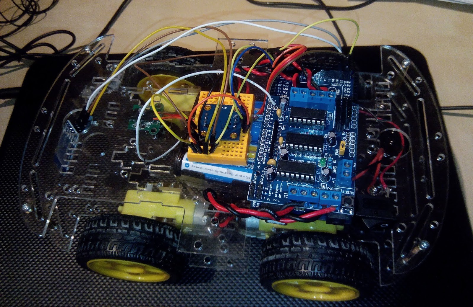
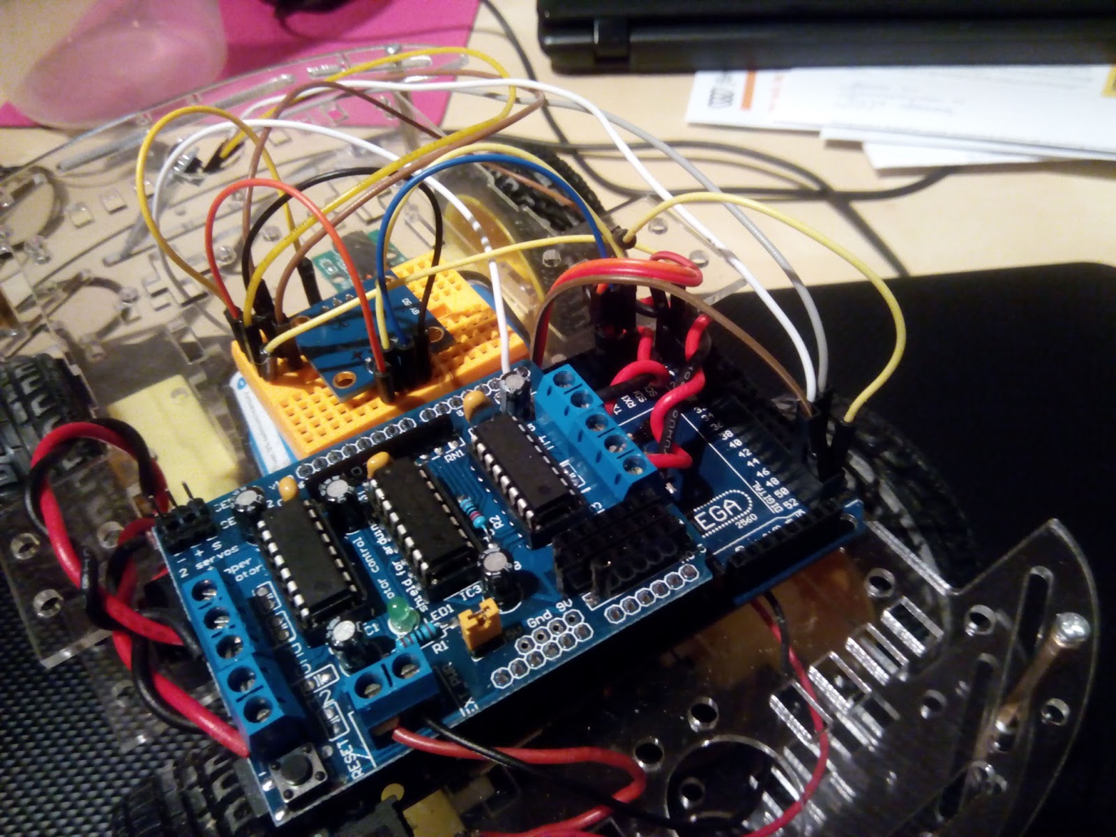
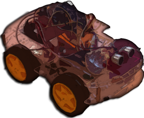
The vehicle consisted of the following components:
- Arduino Mega
- L293D based Motor shield
- L3G4200D gyroscope
- Speed encoder
- HC-SR04 ultrasonic sensor
- HC-06 bluetooth module
- 4 DC motors
- 12V battery pack
They participated in two workshops, approximately 6 hours totally, on Arduino and the libraries. Then, they came up with the wonderful and intuitive idea, to create an Android application which would allow the user to draw a path on the screen and the vehicle to follow this path. The business applications of such a product, were undeniably obvious. It could be utilized in warehouse logistics, in order to be remotely guided inside a building and through corridors in order to pick a specific component and deliver it at a different location. Moreover, it could be used to remotely navigate through hostile environments, such as engine rooms in power plants or even during natural disasters. I was very proud the simple and inexpensive platform I built, could be used as a proof of concept for such critical and complex applications.
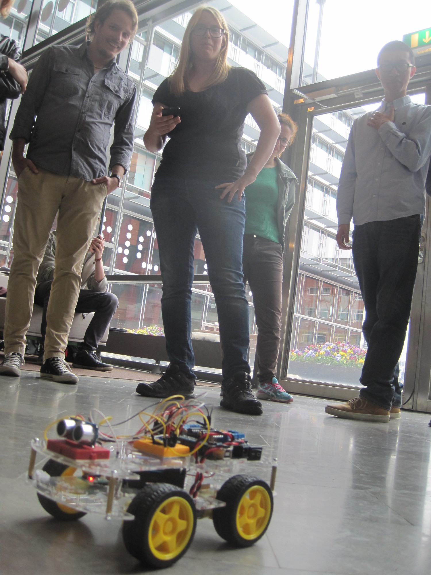
And a wonderful they job they did. They had weekly SCRUM sprints, gradually building up their product’s functionality, working on two fronts, the Android application and the Arduino sketch. Moreover, despite their tight schedule, they managed to enhance it with obstacle detection. When the ultrasonic sensor they installed in the front of the car, successfully determines the existence of an obstacle, then the execution of the path following instructions is halted and a notification appears on the phone’s screen, indicating the location that the obstruction was met. Cool, isn’t it? Imagine if they would have a camera mounted on the car and whenever it would not be able to continue on its path, a camera feed would be initiated, while putting the car in manual control mode, so the user could navigate the vehicle remotely on a safe path.
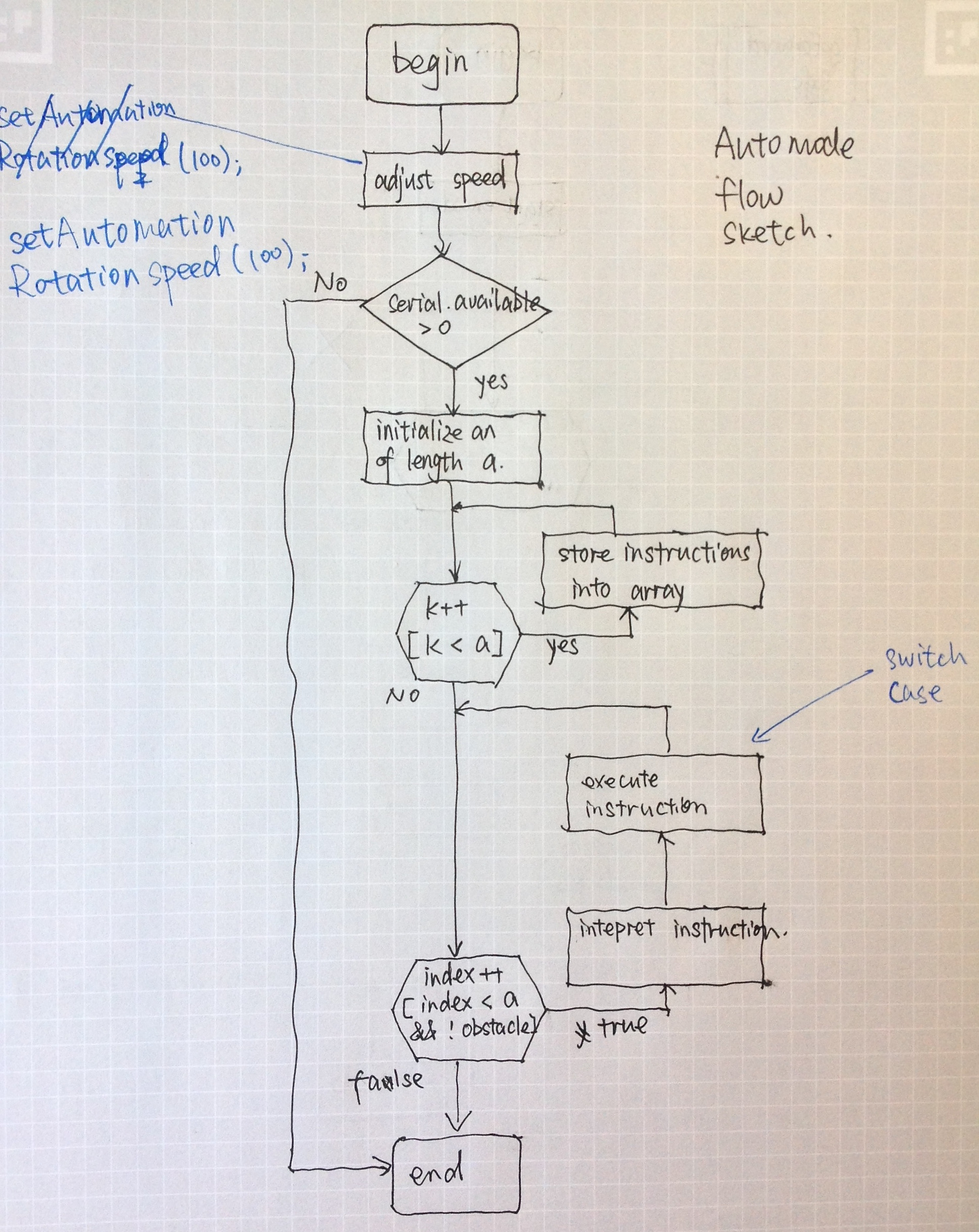
Their Arduino sketch utilizes the Core and Sensors libraries to drive the vehicle and read data from the sensors. It accepts a large set of instructions, which are stored in an array and are sequentially executed. If an obstacle is detected, then the vehicle sends back to the mobile device the instruction which was being executed when the obstacle was found, so the relevant information be displayed on the screen. Consequently, the user can take action or make the appropriate adjustments in the path, i.e. removing or bypassing the obstruction. They were nice enough to include various flow charts and diagrams, so their code and reasoning can be understood easier.
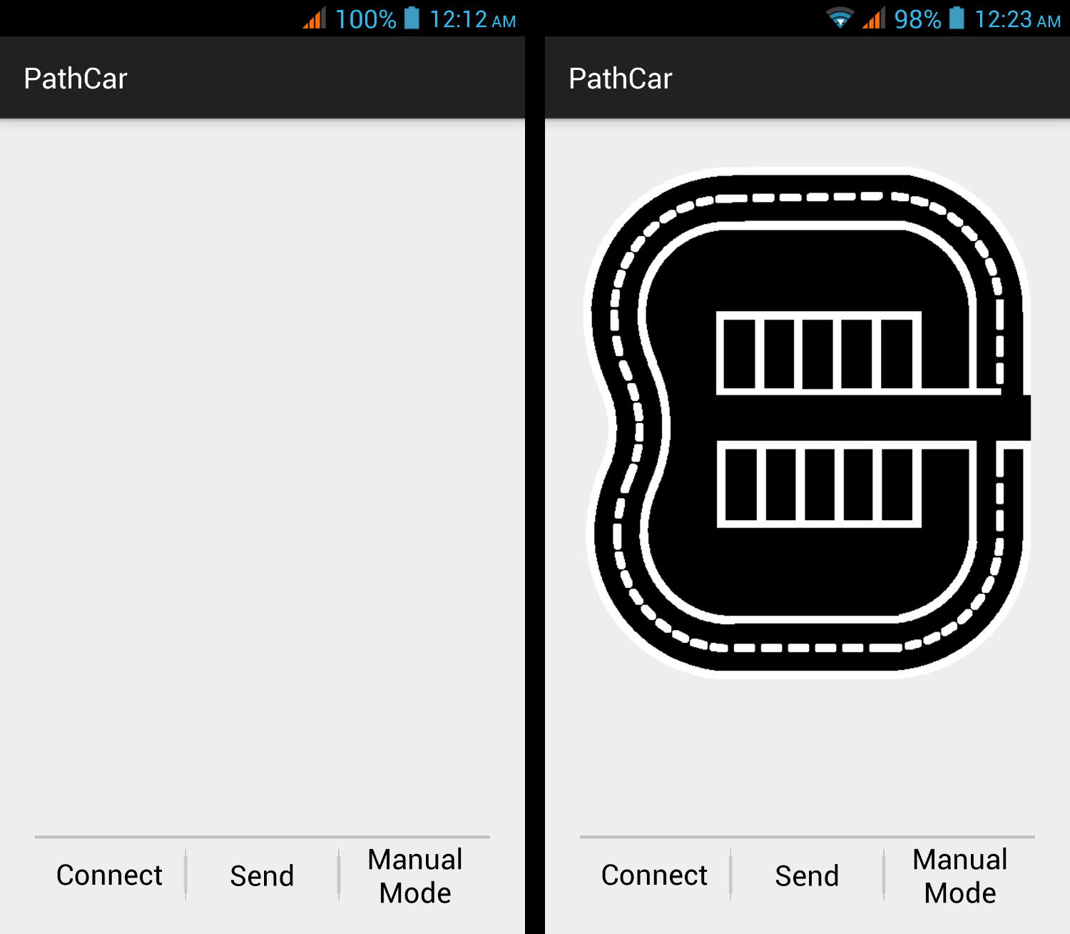
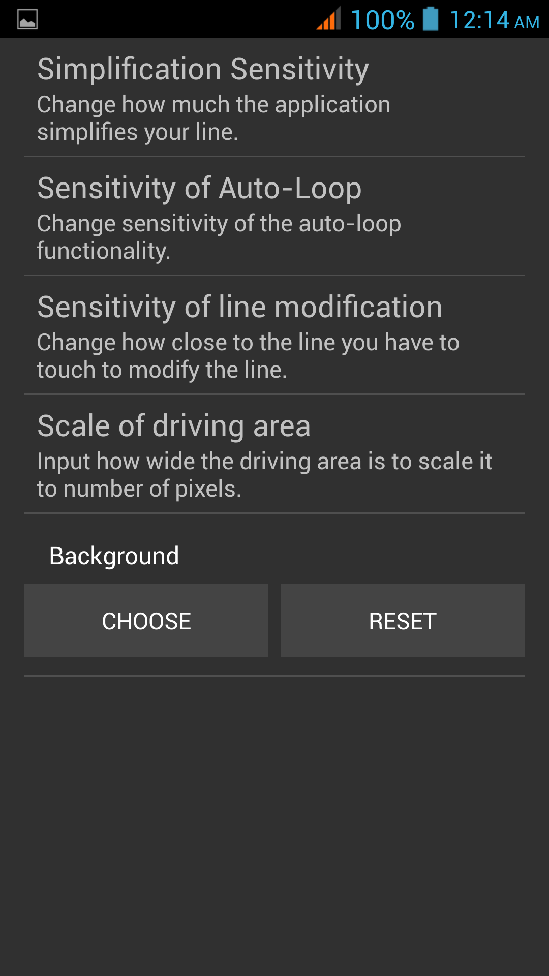
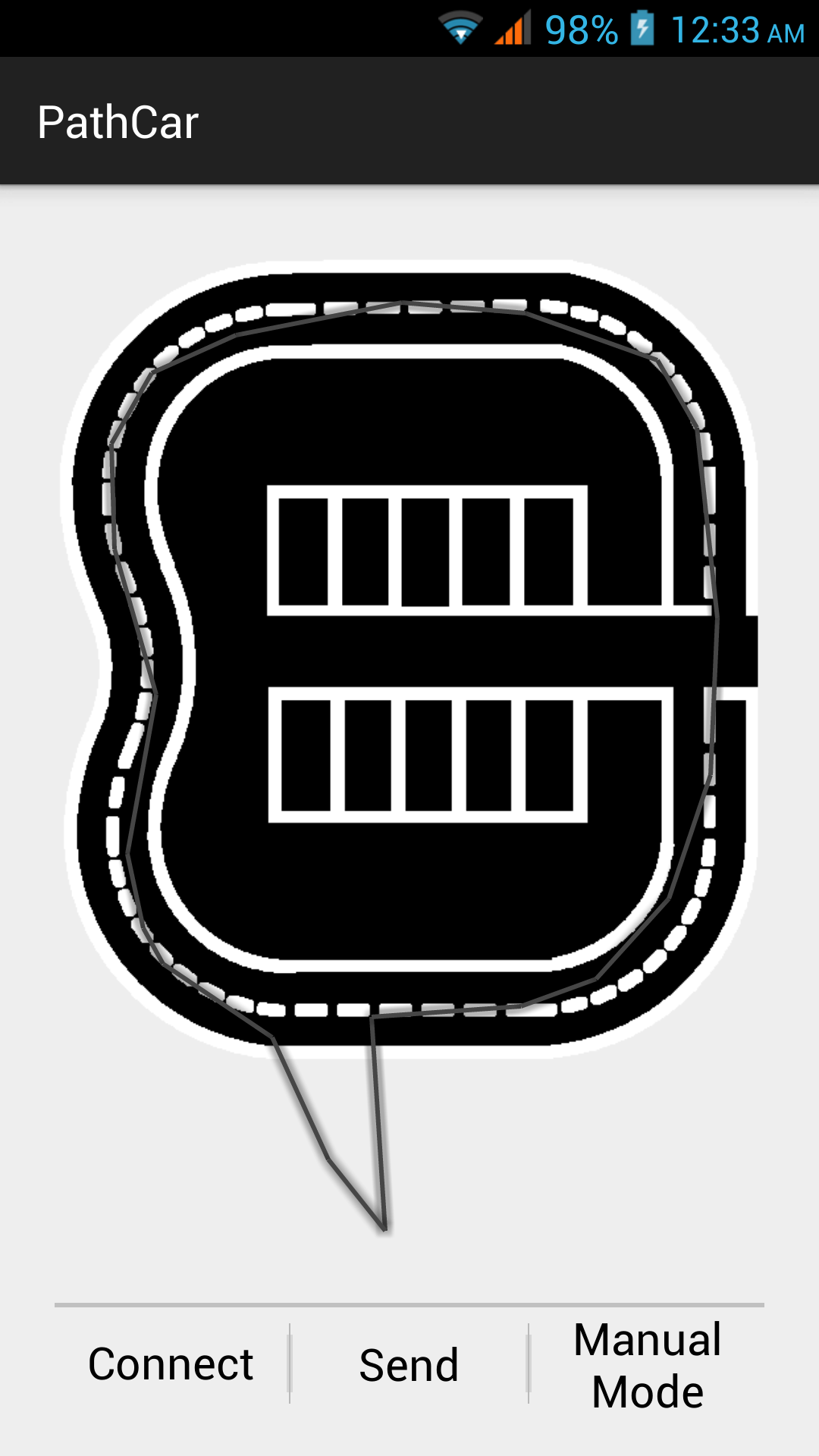
The Android application is neatly designed and allows the user to draw a path on the screen as a line, which is then divided into small straight segments and, depending on the segments’ length and relative angle, the driving instructions are exported. Additionally, it includes features such as the drawn path being auto-completed if the end and the beginning of a line are drawn relatively close, as well as the user being able to correct a section of an already sketched path. There is also a settings page, where the user can set parameters such as sensitivity or the actual size of the area he is intending to deploy the vehicle in. Moreover, there is the option to choose an image, to draw the path over, which could be the blueprints of a factory floor or an aerial photograph of a location. The user, can alternatively opt for a manual mode, using a joystick-like control, which can be seen in the video below.
Overall, this was a great project sporting a lot of potential. I hope they enjoyed it (I know I did) and got valuable experience on creating a physical multi-tier product. Who knows, one day maybe they will get a business proposal to control a bigger and more sophisticated vehicle with their application! As for me, I am planning to improve the platform and the libraries, but more on this when the time comes.
If you want to make one yourself, head over to Instructables.