Simple LED driver board
15 October 2015
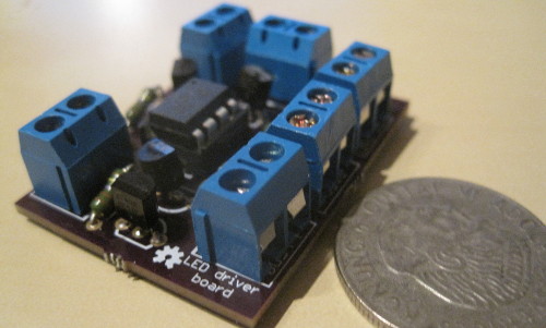
This article is about a simple PCB that I designed and enables the user to drive four separate LEDs (or other circuits) using one signal line. It is based on the ATtiny85 microcontroller by Atmel, which drives four NPN transistors. The aim is to document this board thoroughly, as it will be (hopefully) used by future teams attending the Carolo Cup competition, from Chalmers and the University of Gothenburg.
I’ve realized, open sourcing the SW & HW isn’t enough to make a project sustainable. For others to continue working on it, we must thoroughly document it as well. Therefore, this article serves as an informal documentation attempt of the LED driver board.
A handmade version of this board, was used in the Android Autonomous Vehicle we made last spring. There, we wanted to signal whether the car was turning or breaking and we could not afford to have a line for each LED coming from the main control board. In this project, we are facing the same issue, so instead of soldering a similar board by hand, we decided to design and print one. The popular PCB service OSH Park was used to fabricate the board, where you can also order three copies of it, for 11.20$, including shipping.
The source files, needed to edit or reproduce this board are published under a CC-BY license. The ATTiny85 code is under GPLv3.

Overview
The logic itself is fairly simple, the ATtiny85 triggers each transistor, that acts as a switch when the state of its pins goes to HIGH. In other words, when a pin is set to HIGH, the respective circuit is grounded, therefore closed and the LED (or whatever else you connect there) is turned ON. Finally, do not forget to add a resistor behind the base of each transistor and supply a regulated voltage of maximum 5.5 Volts. A more accurate schema can be found here. A more accurate schema can be found here.
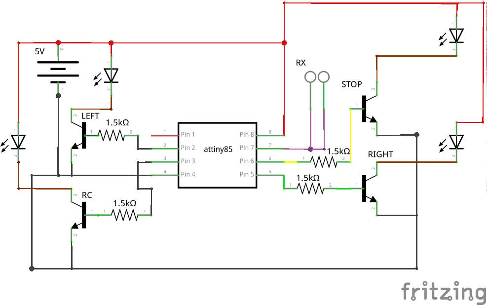 The sketch running in the ATtiny85, allows the blinking of the LEDs in the various modes, without any delay, with the microcontroller being able to switch its state at any moment it receives a valid input. The code is extensively commented, which I believe should make it easier for you to understand.
Next, you can also notice that we have one signal line. This practically is a serial RX (receive), instructing the microcontroller which LED to turn or more precisely, what state to be in. For example if we send over serial the character “r”, it will start blinking the right hand side blinkers. The ATTiny85 does not have dedicated hardware UART pins, so in our implementation, we used the SoftwareSerial library. Notice that only one pin is used. Despite us declaring another pin as RX, we eventually use it for blinking LEDs as there are no more available pins. Well, there is the RESET one which could be used as an IO pin, however it would make reprogramming the microcontroller a bigger hassle.
Materials used
- 6 screw terminals (Sparkfun)
- 4 NPN transistors (BC547)
- 4 1.5KOhm resistors
- 1 ATtiny85-20PU microcontroller
- 1 socket 8 DIP (optional but strongly recommended, so you don’t solder the ATtiny85 directly on the board)
How to program the ATtiny85
It is relatively easy to program the ATtiny85. You can find more info on how to do that here. Note that you do not usually need the capacitor that is mentioned in the instructions. Try without one first.
Room for improvement
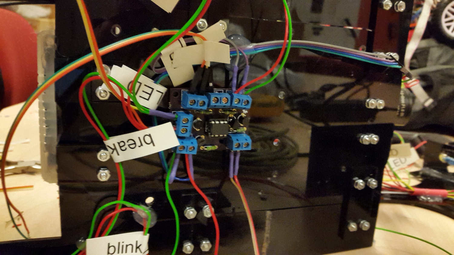
After having this board fabricated and soldered the components on it, I discovered some things that could be done better. I wanted to make this board as small as possible and also versatile. Therefore, I used common screw terminals for the various signals. This is generally not the best solution space and durability wise, as they take up a lot of space and if the cables are stressed, they can be detached. If you want, you can switch to another type of connector, such as JST. A cool addition would be a 3 pin terminal, for the input data line, VCC and GND.
Moreover, in order to be able to instantly recognize which terminal corresponds to which microcontroller pin, I have added some text in front of each of them. The terminals however, proved to be a little bigger than I expected, so they cover most of the text when they are mounted. This makes reading the identification of each terminal a little hard, especially once cables have been attached.
Finally, have a look on how it is currently mounted in our autonomous vehicle, which will compete in the 2016 Carolo Cup, in Germany.
