My personalized Västtrafik bus stop
18 June 2017
In Gothenburg we are fortunate enough to have the local public transportation company, Västtrafik, maintaining its live schedule online and providing a public API for whoever needs to query it for their own applications. Consequently, there are plenty mobile solutions that provide access to the schedule, allow you to plan your trip etc. I have a problem though. In order to figure out when the next bus is arriving, I have to take my phone out, open the application, tap on my bus stop and finally check how many minutes I have left until I miss the bus.
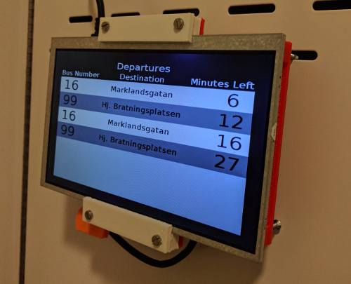
Being the time optimist that I am, I am usually late and cannot afford to dedicate the ~20 seconds that are needed to perform this series of actions. I want to get the information instantly, just as I do when looking at the physical departure screen on the bus stop near my apartment. So I decided to make my own bus stop screen!
So, is this faster than the mobile app solution? Yes and no. The Raspberry Pi Zero W needs around 30 seconds to boot up and display the GUI. Without any optimizations it is naturally slower than my phone. VasttraPi’s biggest advantage is that it allows me to multitask while it is loading. I merely need to tap the button, carry on with my other morning preparations and just glance at the departures screen whenever I need to find out how much time I have left. The device will shut down by itself after 10 minutes.
To make a bus stop screen, the first thing you need is… a screen. A big one for that matter, that is able to receive HDMI input and will not be expensive. I found this 7” LCD screen from China that satisfies the previous criteria for about 22$ including shipping.
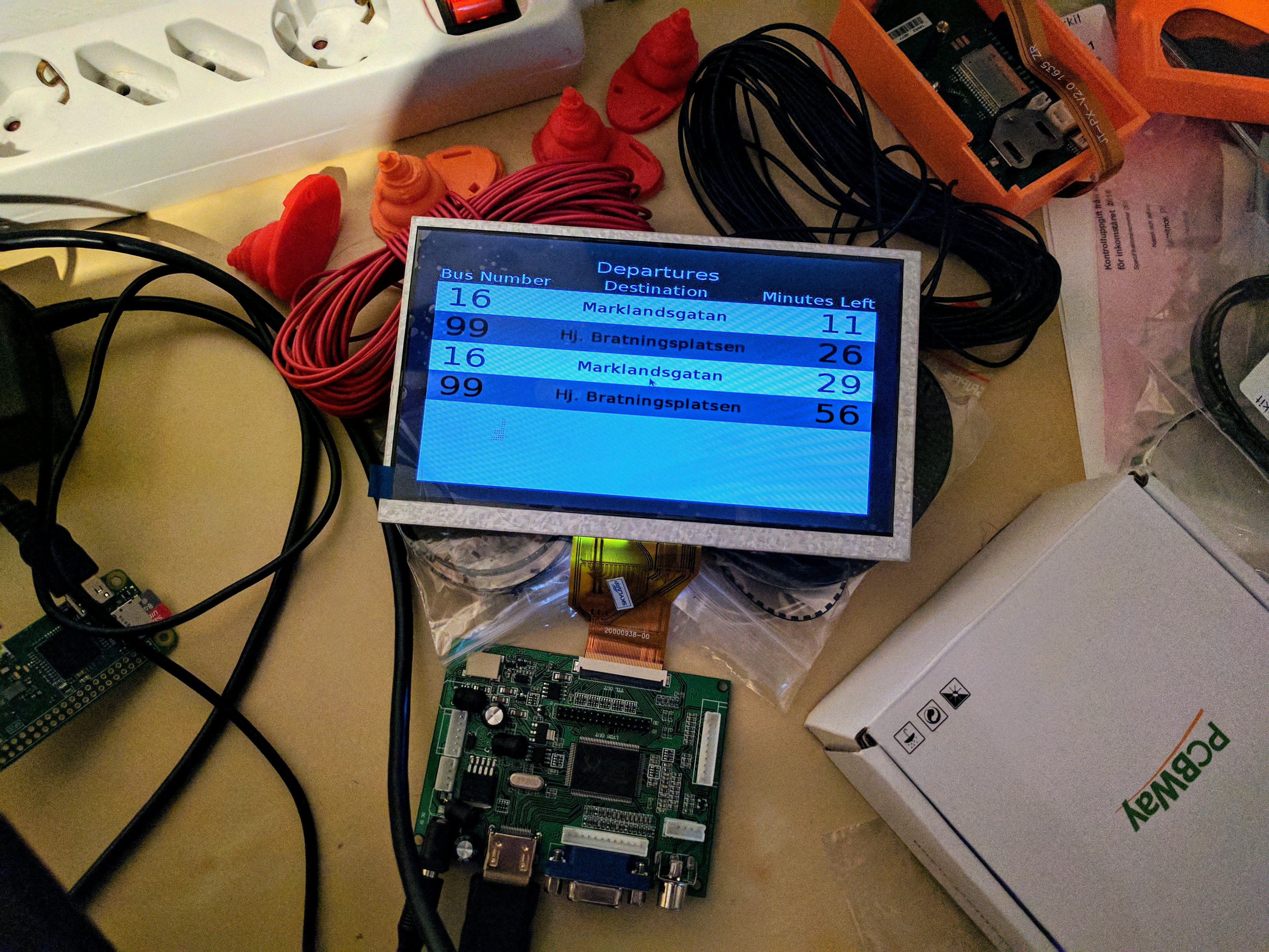
A Raspberry Pi Zero W would be the component that fetches the necessary information from Västtrafik’s API and generates the GUI. This versatile Raspberry Pi model combines a small form factor, low price and on-board connectivity so I have bought a couple of them as they suit a great number of use cases. The Raspberry Pi Zero W is nonetheless a full fledged computer, therefore consumes a considerable amount of power. Neither did I want to have a Raspberry Pi continuously on or have it manually plugged in and out of the power socket every time I use it. The process of turning on and off the Raspberry Pi had to be automated.
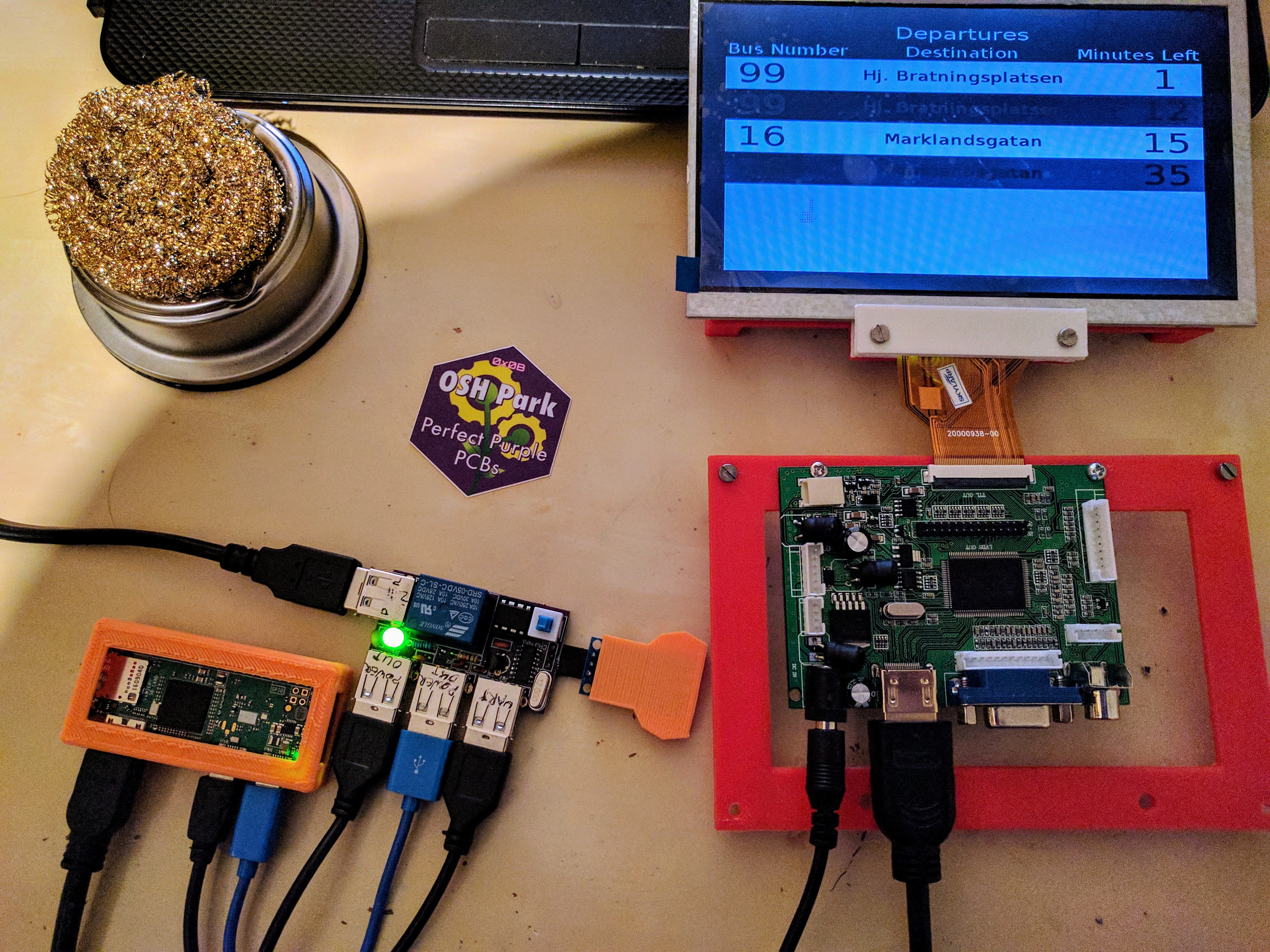
Designing a power control board solved this issue. The board sports a relay that power manages the Raspberry Pi and the driver board for the LCD screen. It is being driven by an ATtiny85 microcontroller that is connected to a capacitive touch button. I also added a CH340 serial to USB chip to establish a line of UART communication between the Pi and the ATtiny. The idea was that the microcontroller could instruct the Pi to gracefully turn off without putting a strain on the Pi’s SD card. It is also there as a future-proofing mechanism, in case we will need to increase the amount of interaction between the system and the user (e.g. display weather information when upon a double tap).
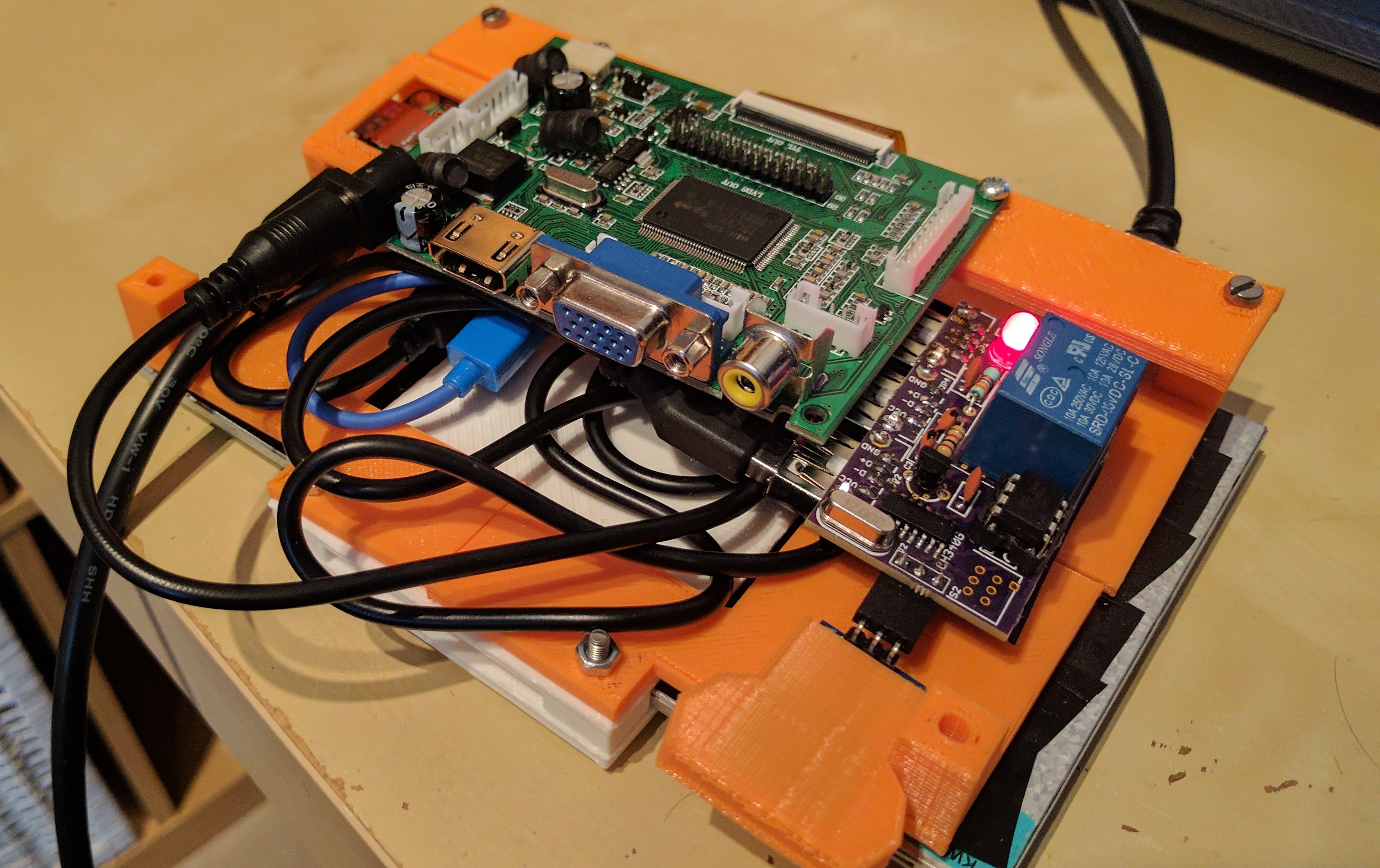
The operation of the ATtiny85 is rather simple. The microcontroller is in a deep sleep state until a user taps the button and the system goes live. Then the microcontroller powers up the system for 10 minutes and extra time is added every time the button is tapped. Once it is time to turn the system off, a command is send via UART to the Pi, next we wait for some time to allow the Pi to shutdown and finally turn the power off and go to deep sleep. I ordered the boards from OSHPark.com and you can quickly purchase your own from here.
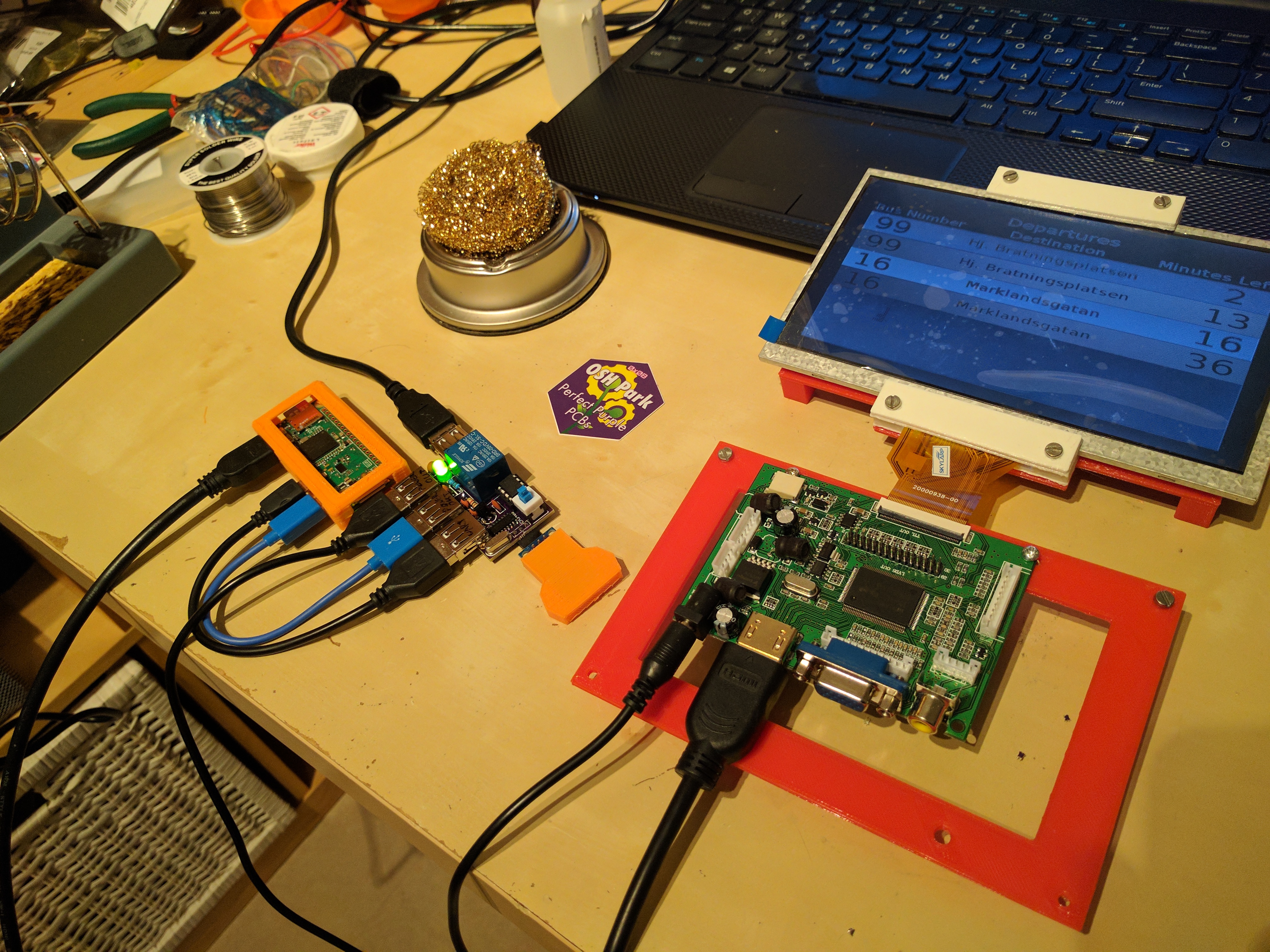
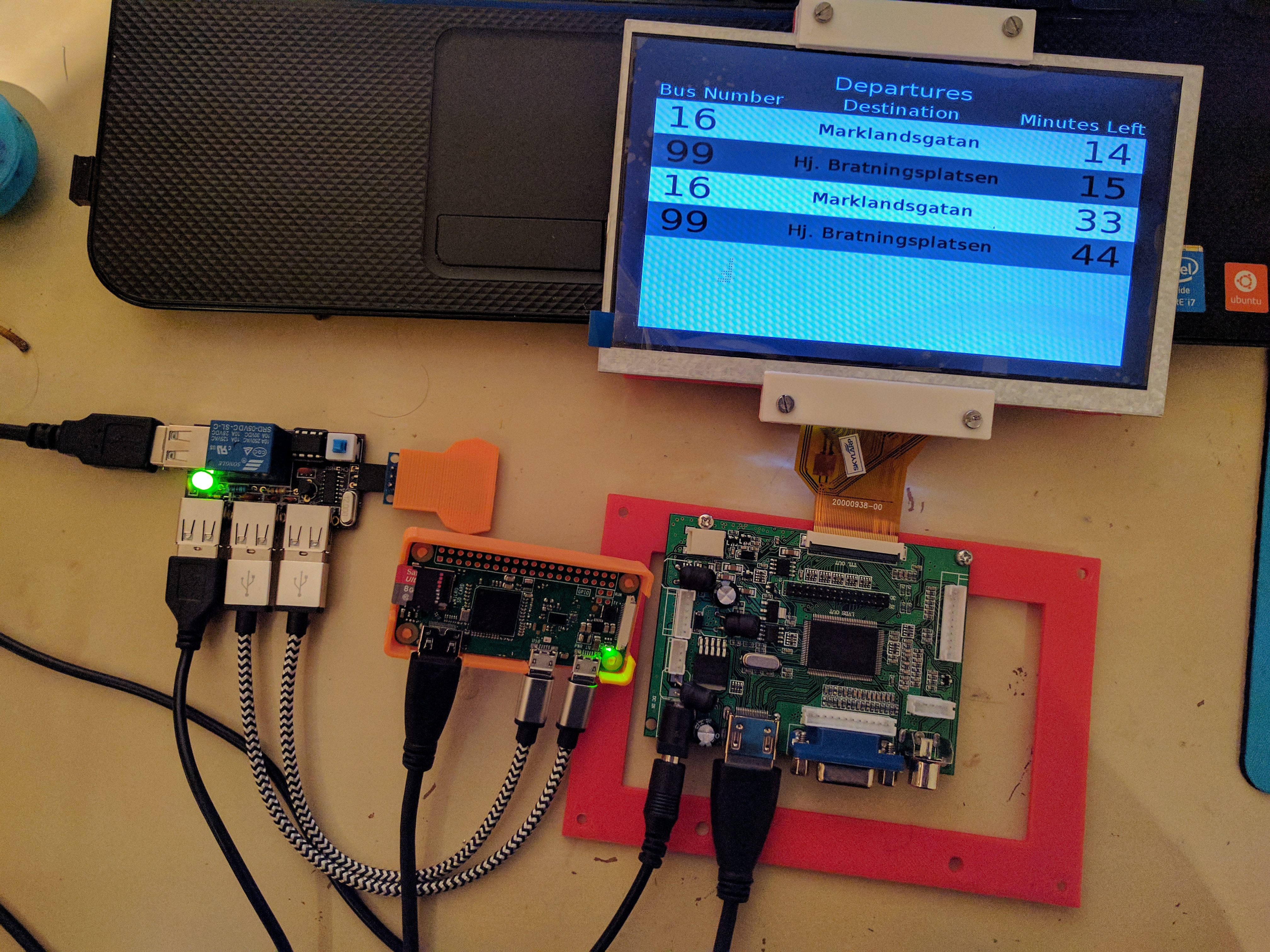
On the Raspberry Pi, a Python script that uses Tkinter to generate graphics is launched on startup, goes full screen and turns off the Pi’s screensaver. Then it periodically fetches bus trips towards the city center from a nearby stop and presents them on the screen. Thus far, the bus station, selected platform and bus line destinations that are displayed are hard-coded, as I do not have the need nor the time to develop a more generic solution. That being said, it should not be difficult to adjust this to other stops and different bus lines.
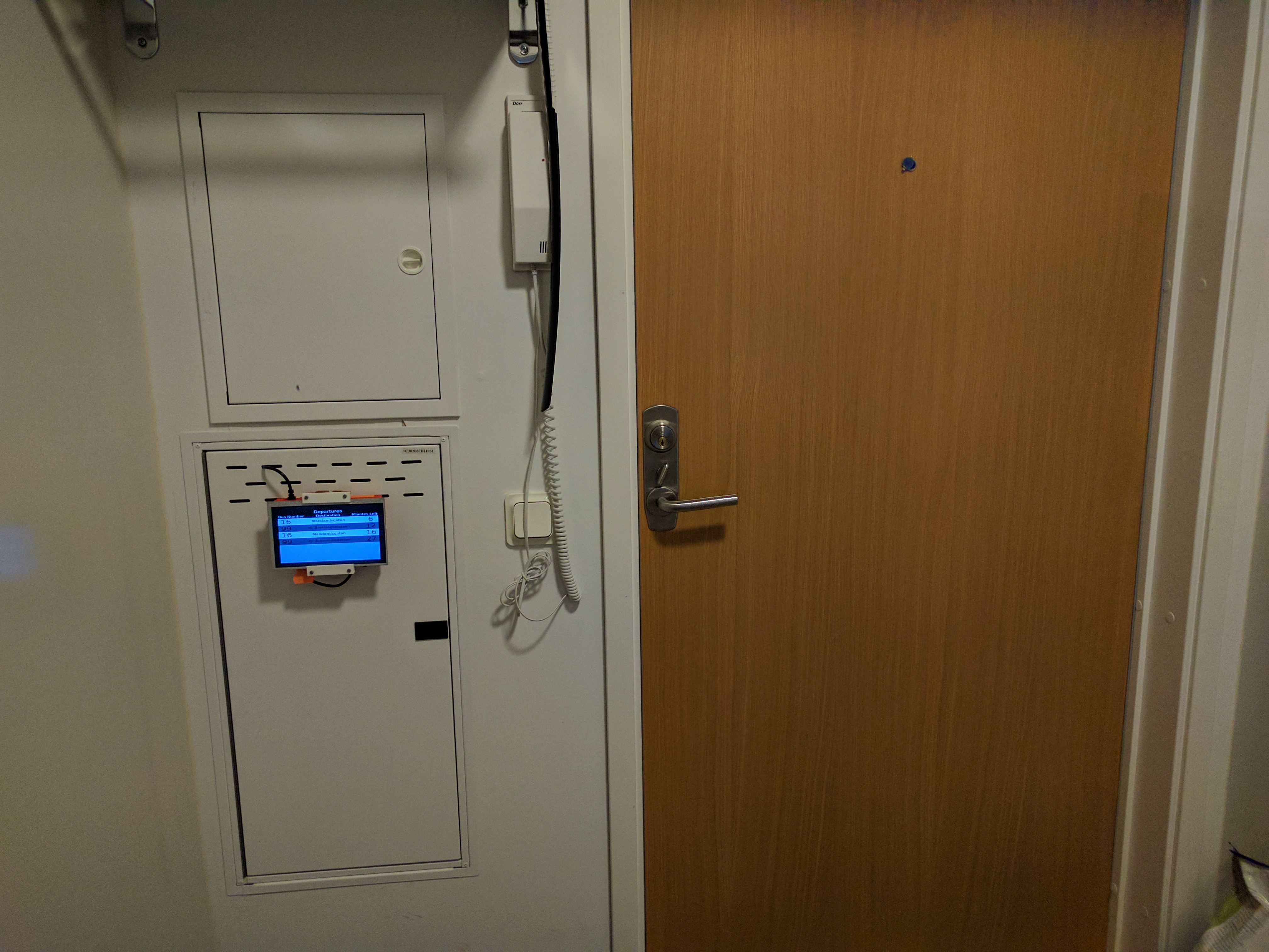
The case to keep everything in place was printed using a ZYYX+ 3D printer. I am not particularly proud of it (the case is nothing special) and do not think it will be very useful to others, so I will not be publishing the 3D models. I will of course mail them to anyone that asks for them. Everything else, that is firmware & hardware schematics for the power control board, the Python script running on the Raspberry Pi and instructions on how to deploy it, can be found on GitHub. In the project’s repository you can also find out how to get your Raspberry Pi’s root as read only with OverlayFS which I personally consider very cool.
