Moltoduino: Extra cores & HIL testing
21 February 2018
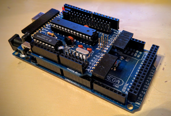
If you are like me and enjoy working on microcontroller projects it is more than likely that, at some point, you wished you had additional processing power, extra pins, parallel threads and so on. One way to tackle this is to get stronger hardware and another to optimize your code. A third is to… stack another microcontroller on top and thus Moltoduino was born!
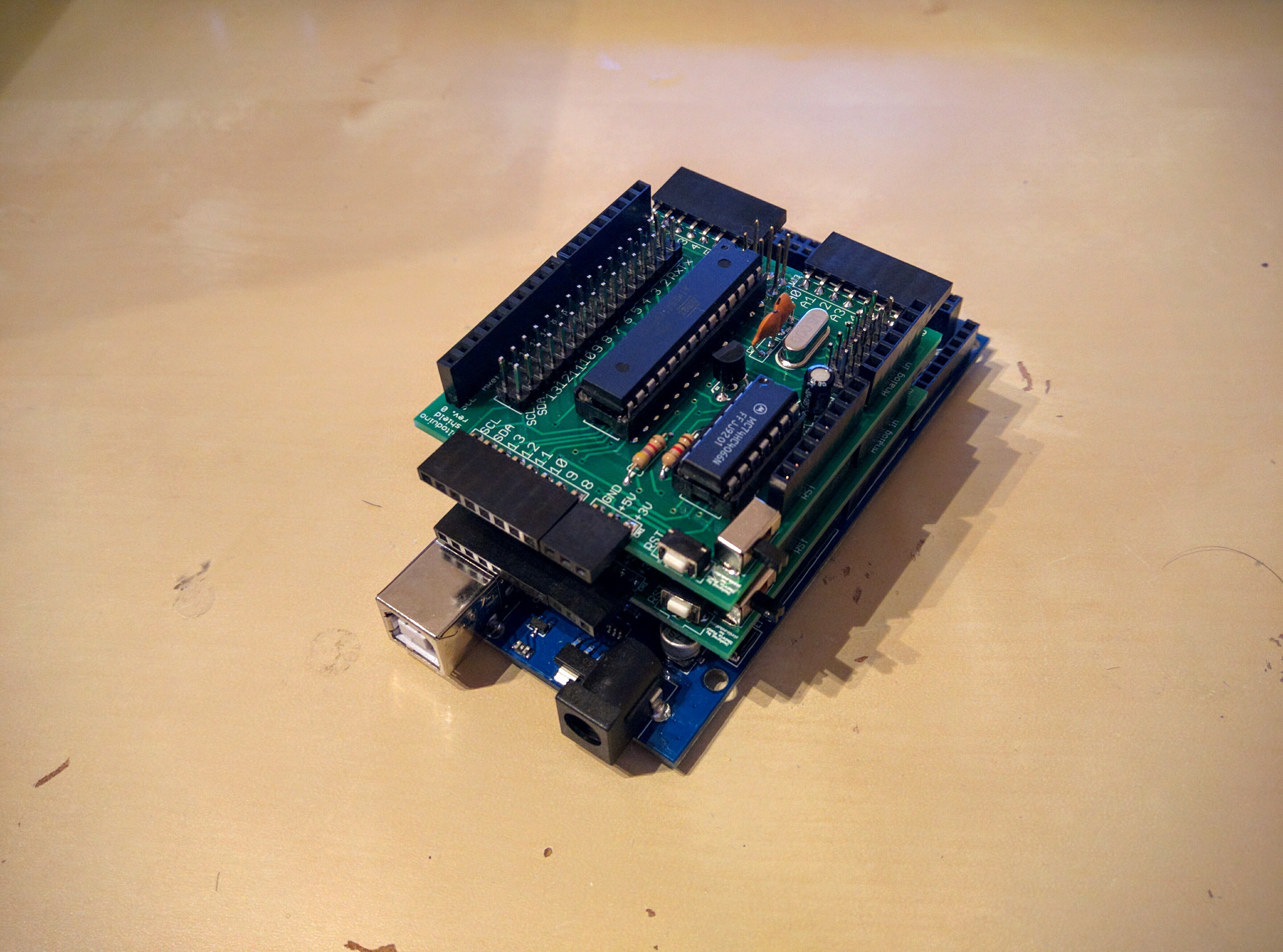
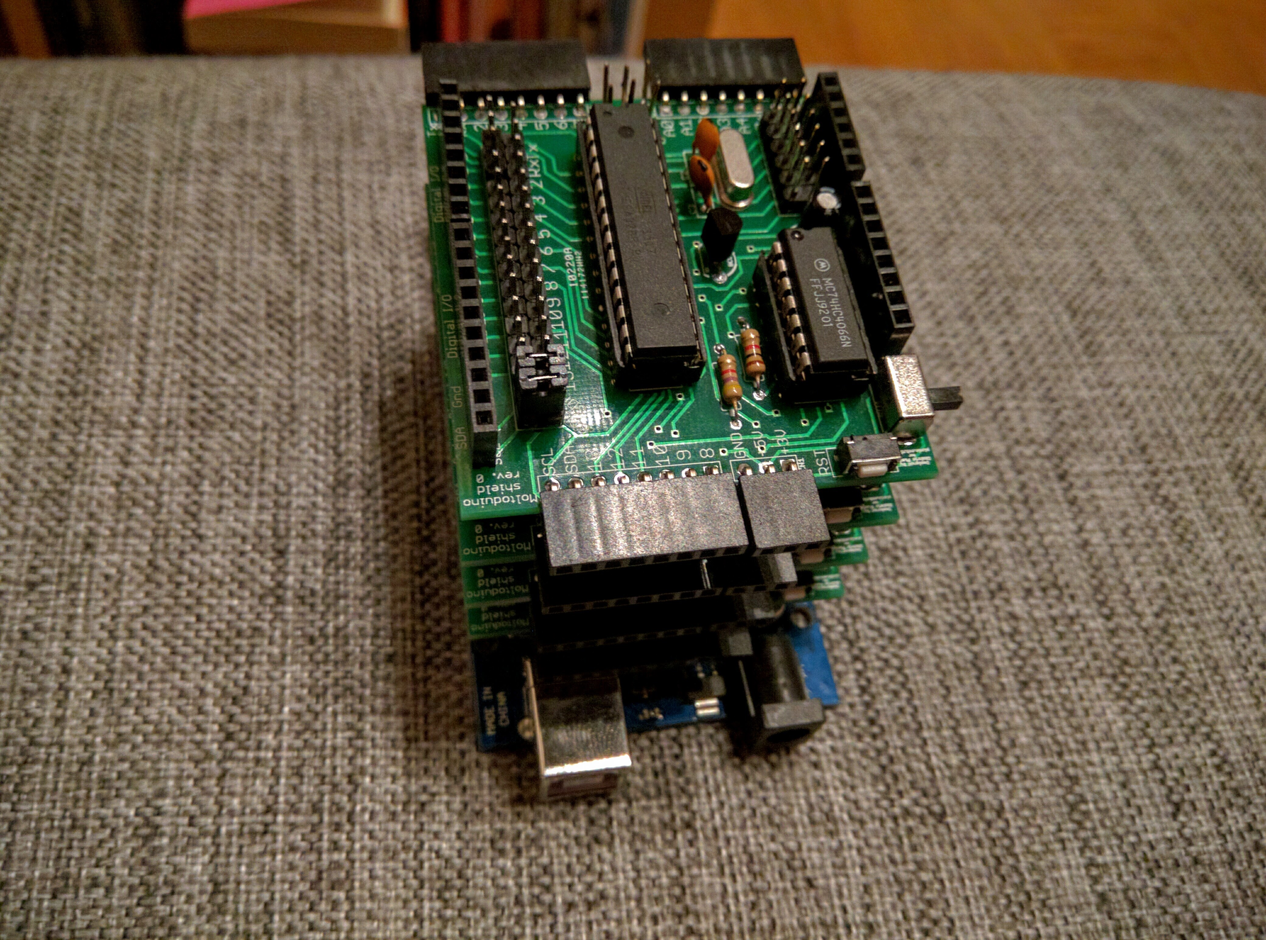
Moltoduino is a shield that allows you to stack multiple ATMega328P microcontrollers on top of your Arduino board. It was first devised as a way to increase the available resources as well as parallelize time and computationally intensive operations without consuming extra space. However, during the development of the shield, a new use case became apparent. Α potentially more interesting one that is!
Moltoduino can be utilized to provide a hobby-grade HIL testing solution for your embedded hobby project. Having two microcontrollers that are easily connected to each other it is possible to conduct HIL simulations. This is achieved by one microcontroller running the production code and the other running the HIL test which generates input for the system under test and reads its output. Such a HIL test fixture allows you to automate system-level testing on your project by mimicking real-world input. This can be a difficult and laborious process, in which case the tester would have to manually provide the environment input and check the output so to verify the system. Take a look at a video I created where I demo the board’s HIL capabilities.
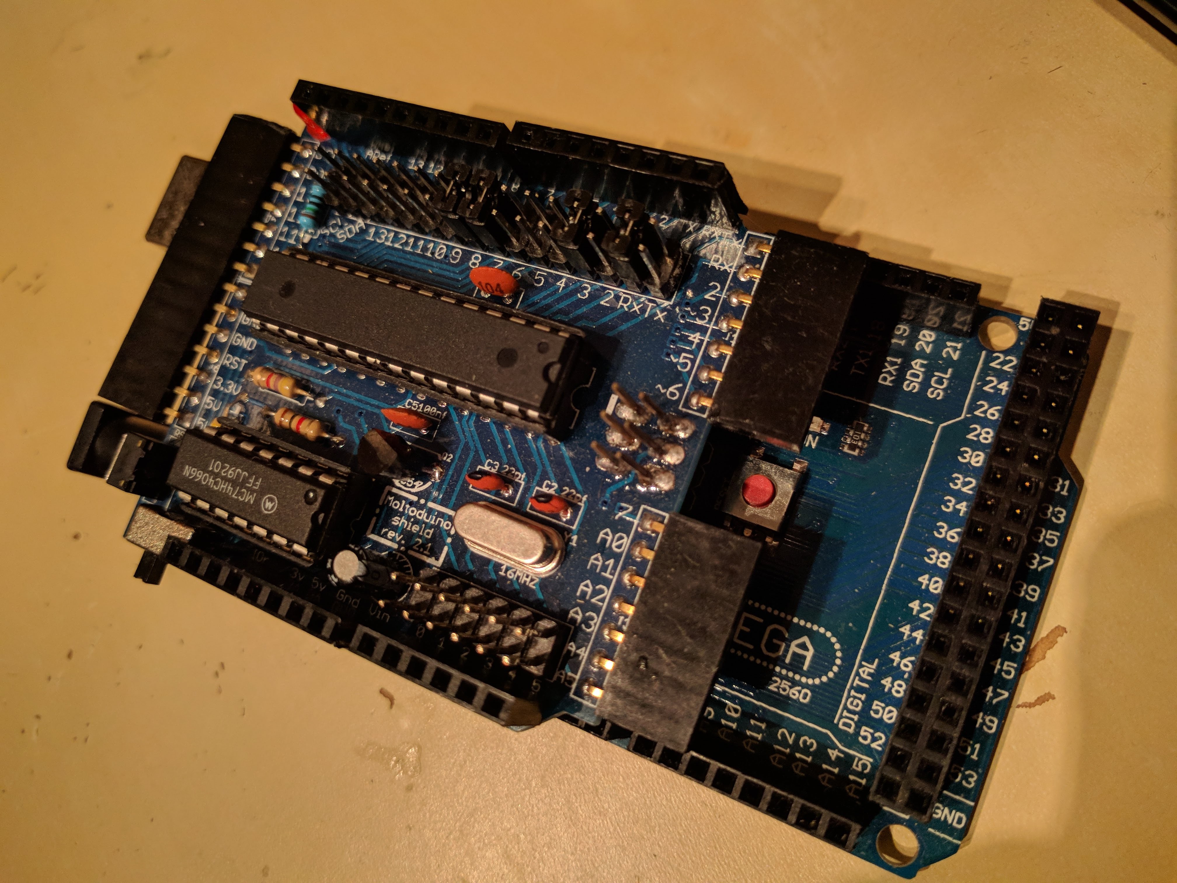
So how does it do all that? As previously stated, the Moltoduino shield is a broken out ATMega328P microcontroller. Hardware-wise, it is a stripped down version of Arduino UNO and in regards to software, they are practically the same. On the shield, the microcontroller pins are broken out in two ways:
- Outwards, to enable their arbitrary connection to different components or other pins via cables. - Inwards, to enable their connection to the respective pin of the bottommost Arduino via jumpers.
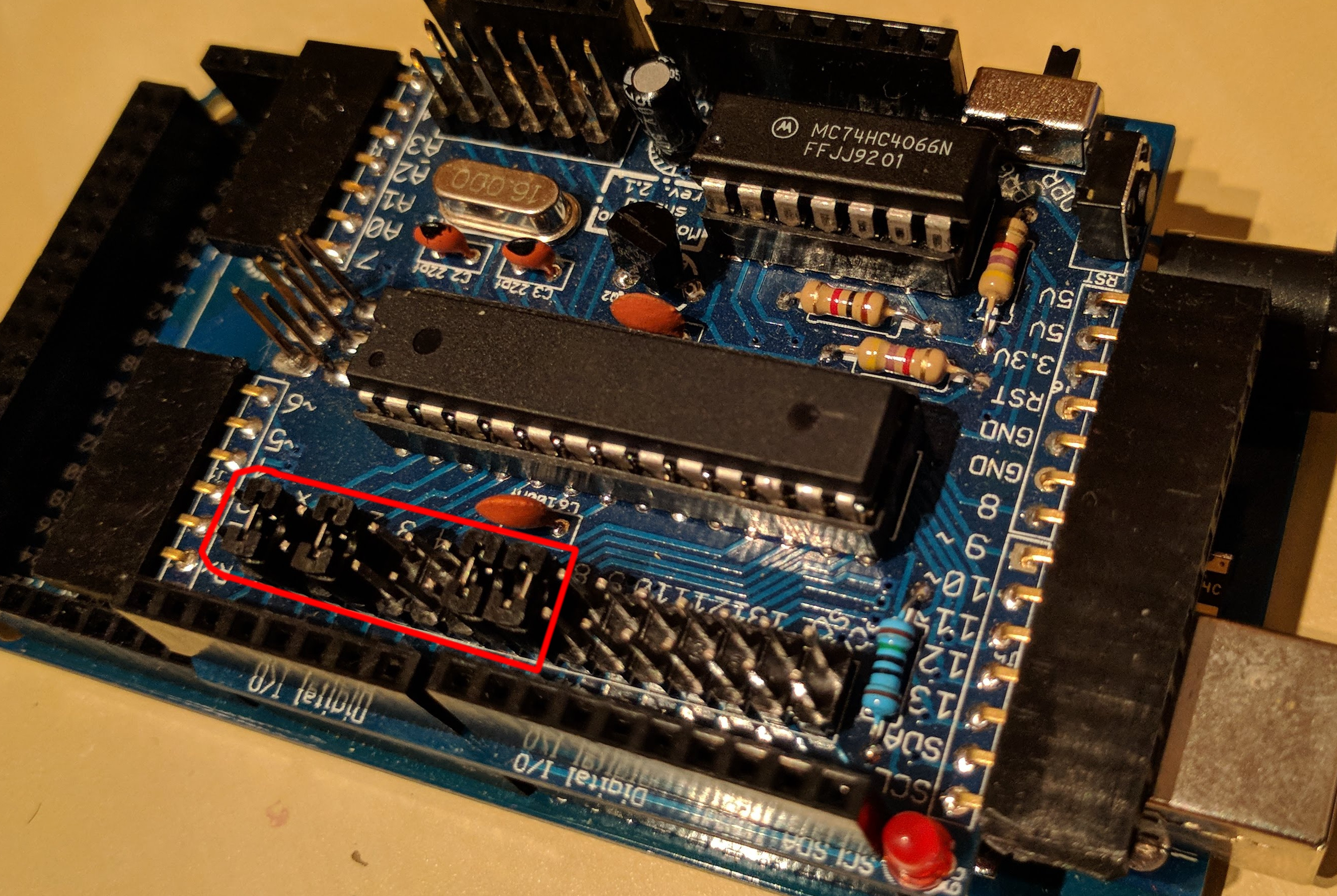
The picture below illustrates how the pins of the shield’s ATMega328P are broken out, highlighting them with green. In red one can find the bottom Arduino’s pins. It becomes apparent that pins that follow the Arduino numbering convention can be easily connected via jumpers (e.g. D1 with D1) regardless of which specific Arduino board is in place (i.e. Mega or Uno). Furthermore, the shield’s pins are also broken on the sides of the board so to be accessible when multiple Moltoduinos or other shields are stacked on top.
Additionally, the firmware on the Moltoduino cores can be easily flashed by flipping a switch that sets them in programming mode and then using the bottommost Arduino as an ISP programmer. In fact you can program multiple Moltoduinos at the same time! It is, inexplicably, very satisfying to watch them all being programmed together.
So, what more can you do with your Moltoduino? Here are some ideas:
- Parallelize time-consuming or time-critical functionality (e.g. reading sensor data, playing sound) - Have a dedicated microcontroller for computationally intensive operations (e.g. Fast Fourier Transform) - Get additional resources, such as I/O pins, external interrupts, Serial port, I2C bus etc - Save physical space needed for applications that require a more than one microcontrollers (e.g. by stacking them instead placing them next to each other)
The project is open source and can be found along with some proof-of-concept code examples on GitHub. This means you can use inexpensive services such as wellpcb.com to build everything yourself. If you have a cool idea on how to incorporate this to a project of yours and would like to get some Moltoduino PCBs, free of charge, do not hesitate to contact me!