Smartcar gets an ESP32 upgrade
16 February 2020
Remember Smartcar, the versatile and easy to use vehicle platform for your hobby-grade projects? It just received a powerful upgrade with an ESP32 as its “brain”, allowing it seamless connectivity via WiFi or Bluetooth. To sweeten the deal, it got new motors and fancy, custom-made chassis!
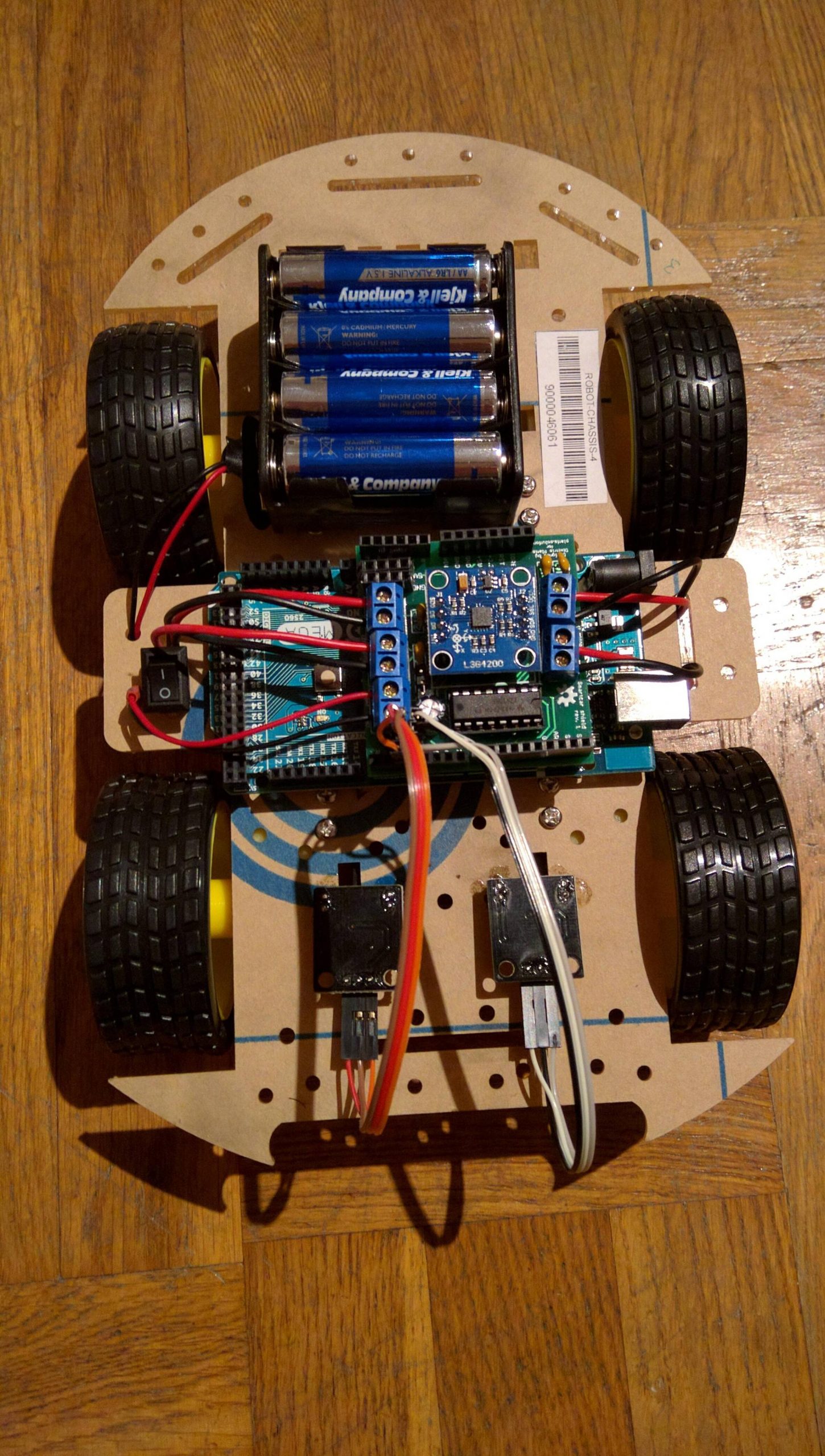
This long due overhaul was driven by the feedback received in the DIT112 course at the University of Gothenburg, where students learn to develop systems with software and hardware components. The (old) DIT112 Smartcars are comprised of off-the-shelf plastic chassis and motor kits (typically sold by Chinese vendors on eBay and AliExpress), an Arduino Mega and a Smartcar shield. The shield controls the motors and has a gyroscope to provide information about the heading of the car. Moreover, the cars have two odometers which give information on how long the car has traveled. The students also receive a variety of sensors to measure distance, temperature as well as some serial to Bluetooth modules. During the course evaluation, DIT112 participants repeatedly expressed concerns over:
- Plastic chassis being in a bad shape or breaking easily
- Motors reacting slowly or very inconsistently to speed adjustments
- Difficulty to connect to the internet as this would have to be done via another node in the system (e.g a mobile phone via Bluetooth or a Raspberry Pi via UART)
During late autumn of 2019, the development of the new hardware platform begun. To address the first problem, we would need chassis made out of some material stronger than the fragile plexiglass of the previous Smartcars. Considering that we would have to mount electronics on the chassis and considering that I already know my ways around designing a PCB, the chassis were to be made out of… PCBs!
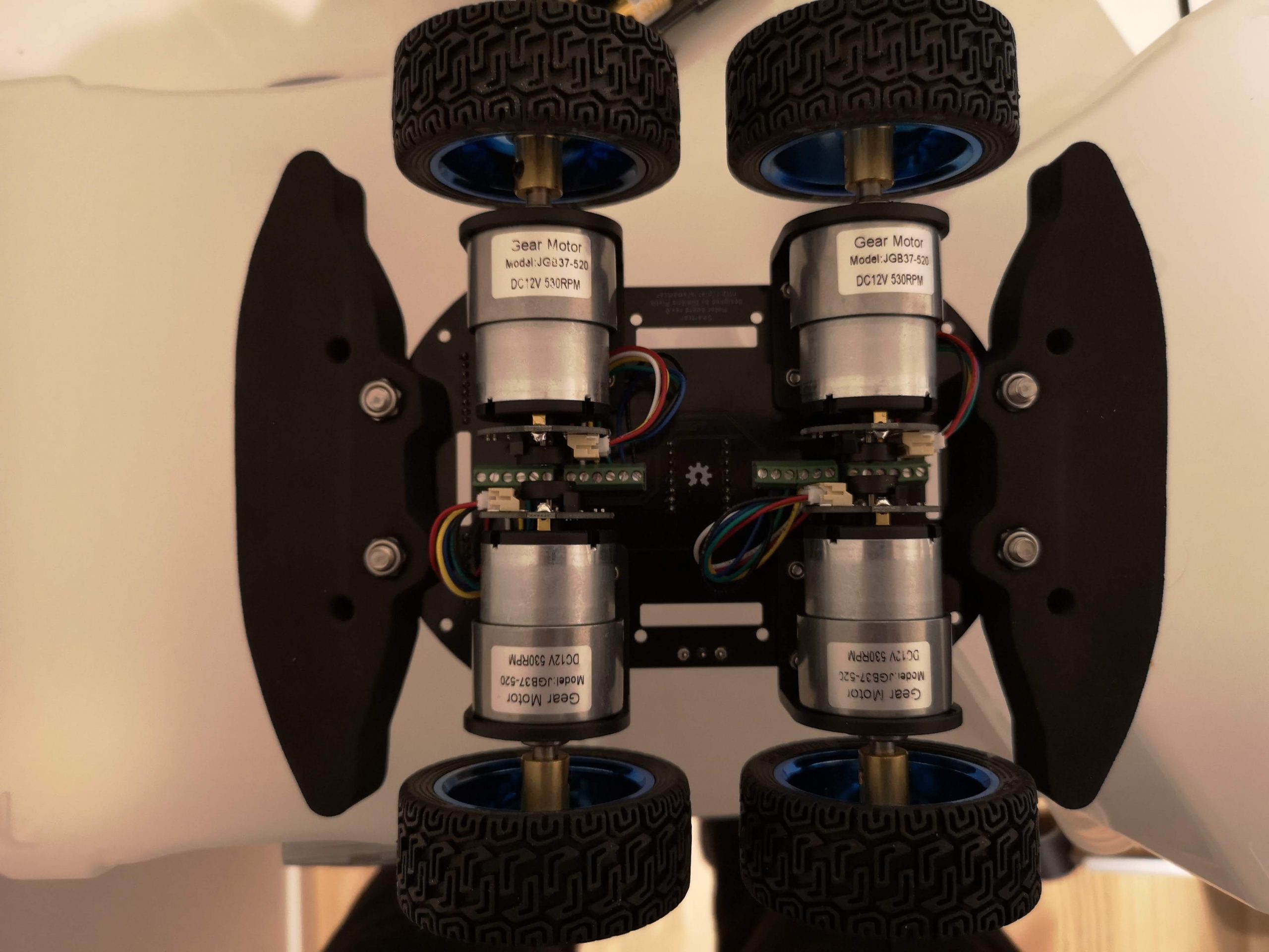
In regards to the motors, there were many options in the market. However, their number was reduced once you introduce the requirement for them to come equipped with odometers/encoders. This decreases the mechanical complexity and the different components necessary to be purchased. We ended up with these motors, which seem come with some brackets for easy mounting as well as directional encoders, meaning that now we’ll not only be able to tell how much each wheel has moved but also towards which direction.
Their only “drawback”, as you can see in the image below, is the harness they came with was too long so I had to chop off the excess cables and expose the wiring manually. If someone would want to save themselves the trouble, they could utilize services such as wiringo.com.
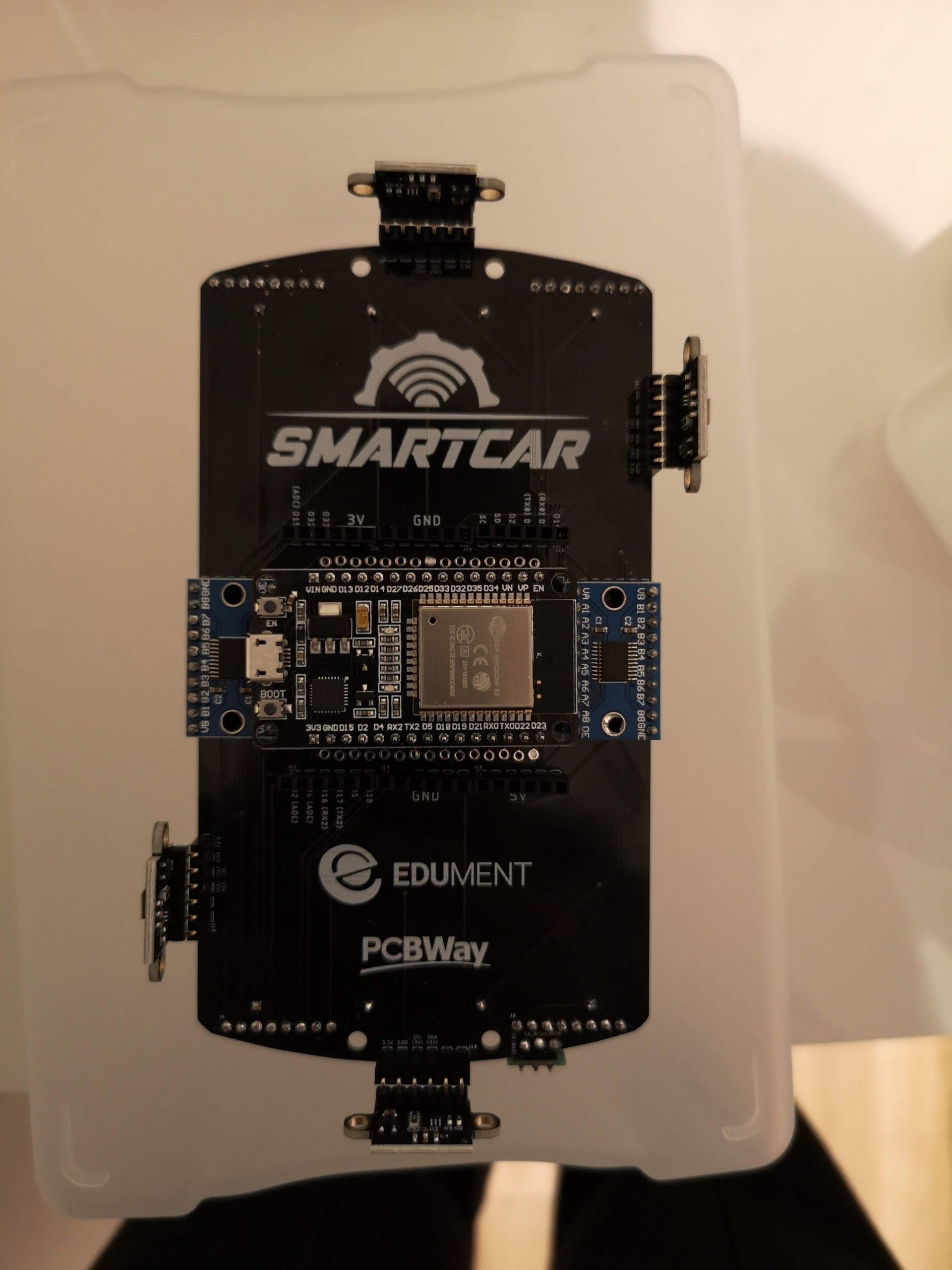
The microcontroller of choice: The mighty ESP32 which offers WiFi connectivity and, unlike its ESP8266 predecessor, comes with more GPIO pins and Bluetooth. ESP32 has some fundamental differences in the way it works compared to AVR microcontrollers. As a result, it does not fully implement the abstraction layer proposed by the Arduino API. Thanks to those differences not being too big as well as the platform-agnostic architecture of the Smartcar library, rather few software changes were necessary to get the library to compile for ESP32.
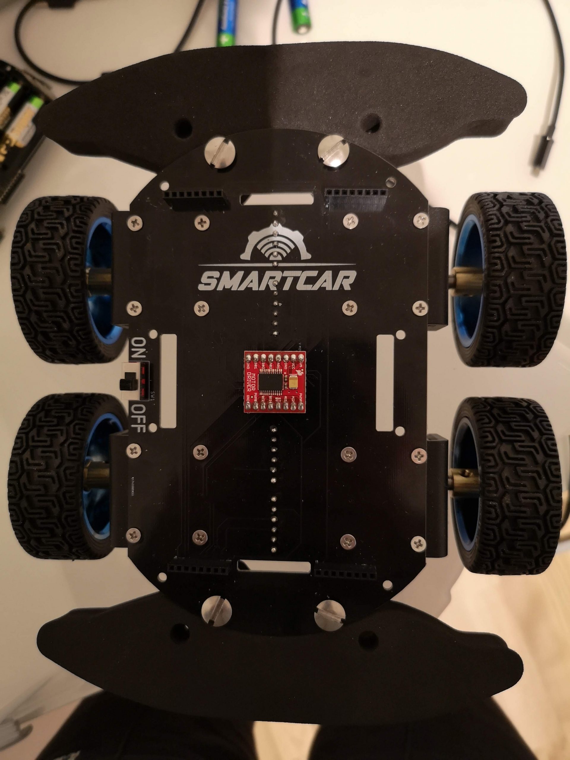
However, there’s an issue with ESP32. It is a component that works with 3.3V signals, meaning that many cheap sensors that operate with 5V logic would either not function properly or damage the microcontroller. To enable Smartcar users to interface their vehicles with 5V components, logic level shifters would have to be included. The TTL level incompatibility additionally meant that the L293D motor controller used on the shield could not be in the picture anymore since it is not specified to work with 3.3V signals. After all, the particular driver is considered outdated and inefficient, therefore it was a perfect opportunity to replace it with a module based on the TB6612FNG dual half-bridge.

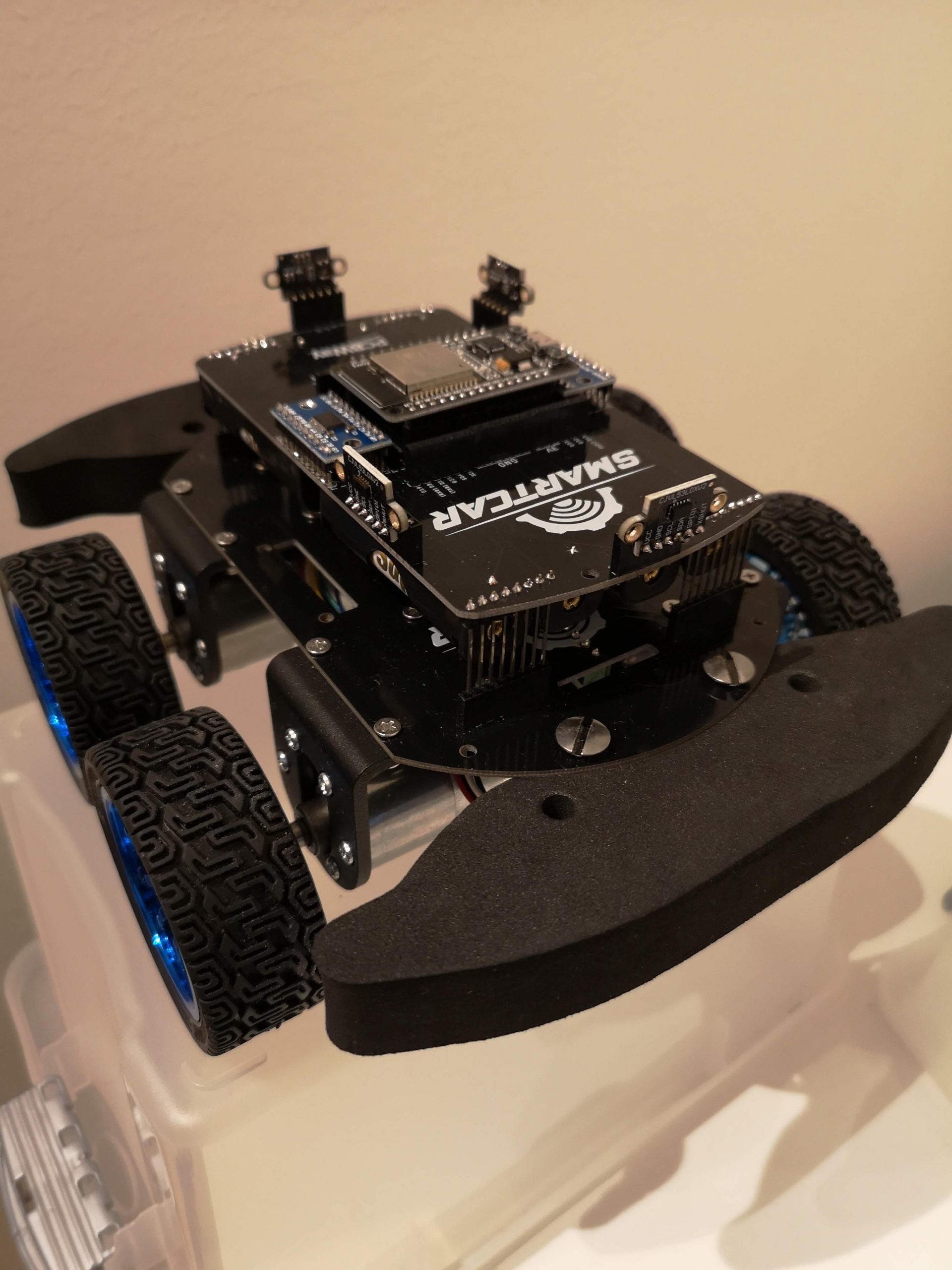
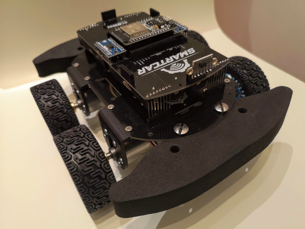
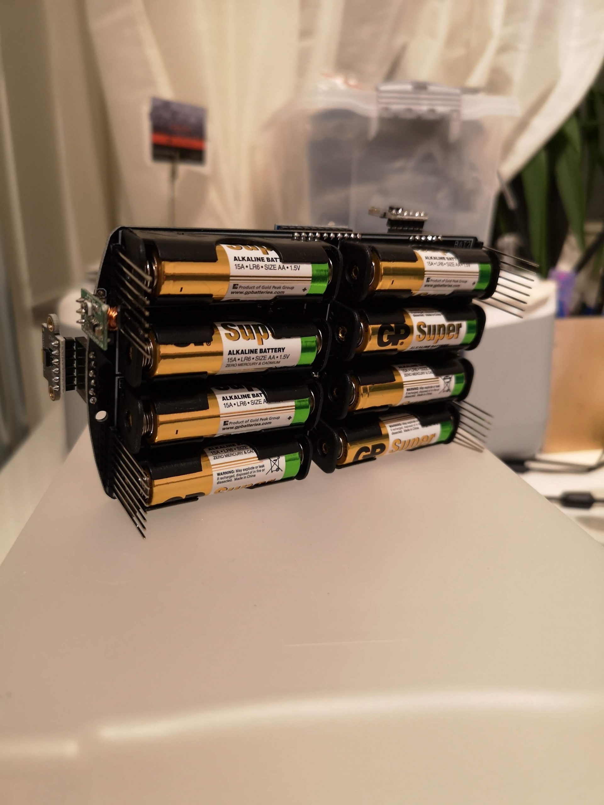
After selecting the hardware components and doing some early prototyping on a breadboard to decrease the probability of last-minute surprises, a stacked design was chosen. This meant two boards on top of each other. The bottom one referred to as the “motor board”, includes the sockets to connect the wires coming from the motors, the motor driver as well as the screw holes for the motors to be mounted. The upper one, aka the “modules board”, houses the batteries, the microcontroller, the TTL level shifters, the gyroscope, and various female pin headers. This design choice minimizes the size of each PCB since the modules board does not to be as large as the bottom one. Additionally, it exposes as much area as possible on the top board as opposed to a solution where everything was cramped onto a single (gigantic) PCB.
To summarize, the new platform’s features are:
- WiFi & Bluetooth via an ESP32 microcontroller
- Differential driving with four motors (controlled in pairs)
- Heading/orientation readings via a GY-50 gyroscope
- Traveled distance, speed and direction readings via two directional odometers/encoders
- Compatibility with 5V components and sensors via TTL level shifters
- 8 AA batteries
- 5V regulator
- Sockets for 3.3V logic pins (optional)
- Four sockets for VL53L0X LIDAR sensors (optional)
- Get up and running in zero time with the Smartcar library
If you would build 10-12 Smartcars, the cost per vehicle is around 60$ if everything is purchased from China. The most expensive components are by far the motors since they cost around 12$ each. If you have any motors in mind that are cheaper and offer similar features, please let me know.
The students will be the ultimate judges of the improvements and I can’t wait to see what cool things they build later in spring. So far, I’m very happy the way the new software and hardware has turned out. Possible improvements include getting a stronger power source. I’ve noticed that if motors happen to pull too much current (e.g. due to them being obstructed) then the system may reboot or become unstable. We are going to buy good quality rechargeable batteries so hopefully, it will not be a frequent issue.
The designs for the new platform along with a detailed list of the necessary components can be found in the Smartcar repository along with the Arduino library. If you are planning to build a Smartcar yourself, feel free to contact me as I have some tips on how to assemble things together. Last but not least, I would like to thank PCBWay and, my employer, Edument for supporting the development of this new platform.