SMCE: Your Arduino car emulator
25 September 2021
With the pandemic ongoing, hardware isn’t only difficult to source but also hard to collaboratively work with safely. In the case of smart miniature vehicles, the number of available units is inherently limited and so is the “environment” we deploy them in, e.g. a race track or an obstacle course. How do we work around the hardware resource scarcity? We digitalize the resources!
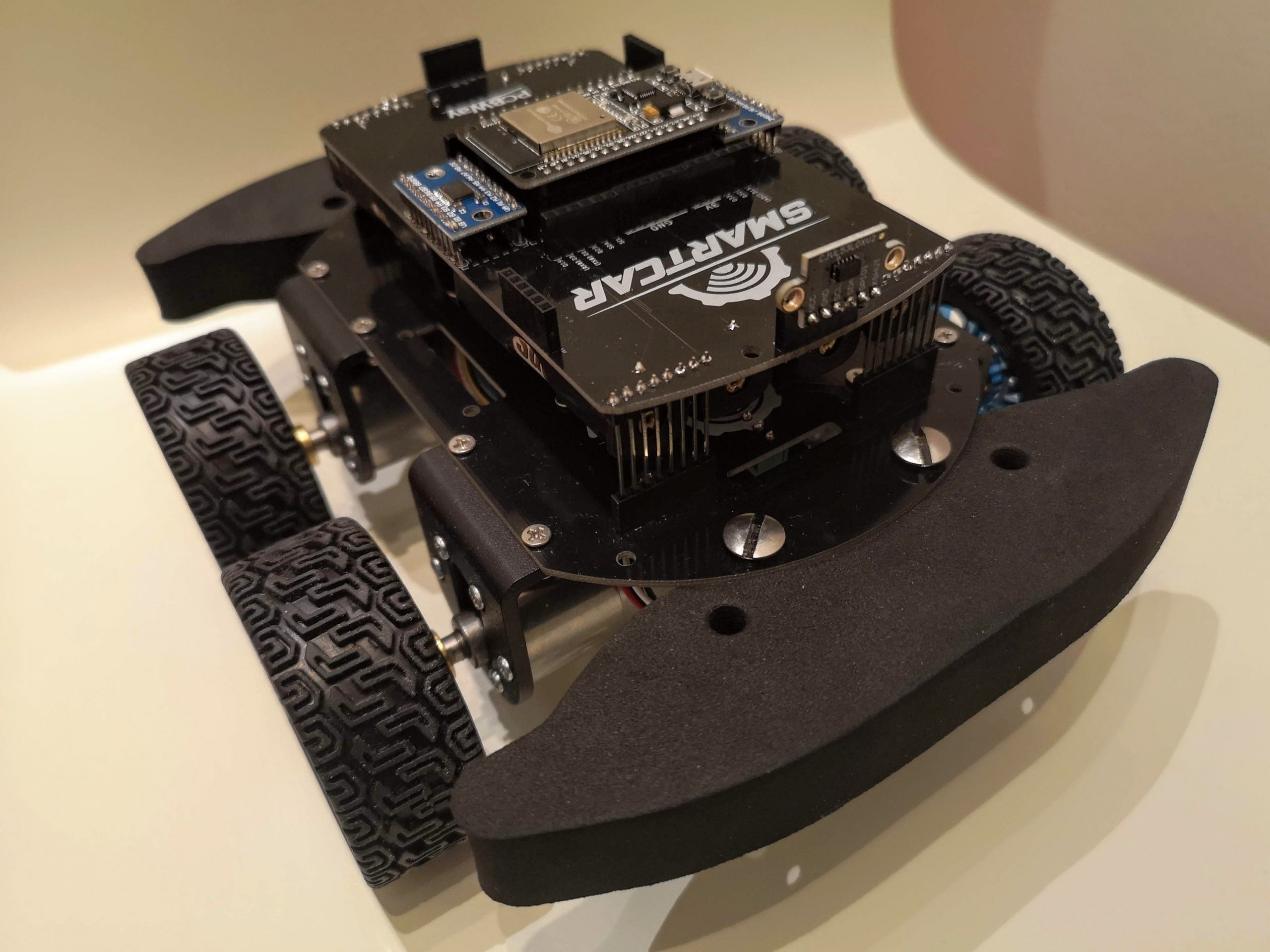
SMCE is the digital twin of the
Smartcar platform along with a cool and customisable
3D world for your rover to roam in.
The core concept is that you write Arduino code that runs on both the real hardware as well as
the virtual environment. This way, the need to have exclusive and frequent access to the car can be
either alleviated or drastically decreased. Ideally, the emulator allows limiting the unavoidable
engagement with the physical car, to the point a team of developers may develop their features on
the emulator and only access the real hardware to verify them.
Working with a virtual representation of a cyber-physical system isn’t only valuable during a pandemic.
Those of us that work with embedded systems, may painfully recognize the adverse impact of being
blocked due to lack of hardware availability.
In this post, I will show you how to get started with SMCE as well as many of its features.
If you would like some inspiration about what you could use the software for, check out how our students
utilized SMCE to emulate Arduino vehicles.
About SMCE
Before diving deeper in the emulator, let’s clarify what SMCE isn’t: A 3D environment for your
super custom hobby project that uses all kinds of exotic sensors and third-party libraries.
Out of the box, the emulator is there to support users of the Smartcar library
and accommodate their typical use cases and sensor setup.
The emulator will not work only with the particular library, however, your life will be much easier if
you use it. And I am not saying this just because of the emulator. It comes with a lot of
examples, it’s versatile and overall a very easy library
to work with, you should give it a try!
Moreover, I should note that the emulator is not made or maintained by me, so please don’t contact me
asking for support. It is developed by two very talented ex-students of mine,
Ryan Janson and
Ruthger Dijt. You can contact them by
creating an issue or starting a discussion on one of the relevant GitHub repositories.
SMCE is comprised of two parts: The “front-end” (smce-gd)
and the “back-end” (libSMCE).
libSMCE is the library responsible for compiling and running the Arduino sketches on your computer.
This cross-platform C++ library provides its consumers the ability to compile and execute Arduino sketches on a hosted environment, with bindings to its virtual I/O ports to allow the host application to interact with its child sketches.
smce-gd depends on libSMCE to visualize the sketch execution in a colorful virtual 3D world and the interaction
with the surrounding environment. Unless you are planning to do something “smart”, extend or contribute to the
project etc, smce-gd is the software you shall primarily care about.
For this tutorial, I will be using the 1.3.1 release
of smce-gd, running on Ubuntu 20.04.
Get started
To install SMCE on my Ubuntu laptop, I followed these
instructions found on
smce-gd’s Wiki. A really cool thing about SMCE is that it will work on your computer. SMCE can be
also installed on Windows or
MacOS.
If SMCE was installed correctly, you will be greeted by the following screen:
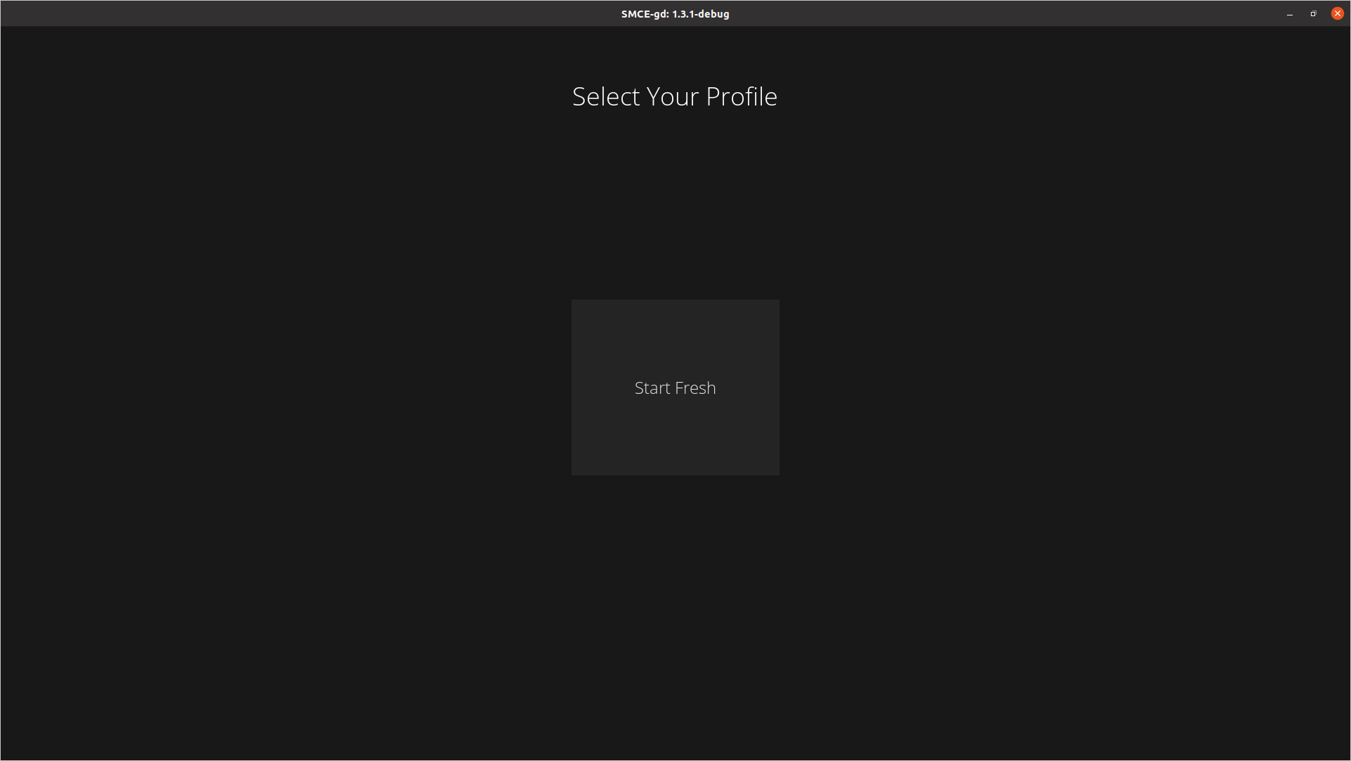
Select the Start Fresh option and in the next screen click on the + sign.
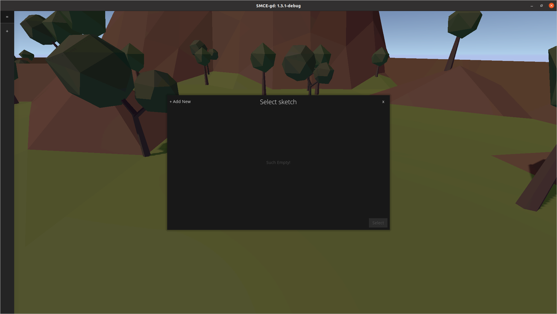
Then it’s time to select the code that runs on the Arduino. I recommend starting with the
manualControl.ino
sketch found in the examples of the Smartcar library. An easy way to get the example is to download the
Smartcar shield library via Arduino IDE’s library manager and then locate it on your disc.
Let’s have a look at the sketch:
#include <Smartcar.h>

const int fSpeed   = 70;  // 70% of the full speed forward
const int bSpeed   = -70; // 70% of the full speed backward
const int lDegrees = -75; // degrees to turn left
const int rDegrees = 75;  // degrees to turn right

ArduinoRuntime arduinoRuntime;
BrushedMotor leftMotor(arduinoRuntime, smartcarlib::pins::v2::leftMotorPins);
BrushedMotor rightMotor(arduinoRuntime, smartcarlib::pins::v2::rightMotorPins);
DifferentialControl control(leftMotor, rightMotor);

SimpleCar car(control);

void setup()
{
    Serial.begin(9600);
}

void loop()
{
    handleInput();
}

void handleInput()
{ // handle serial input if there is any
    if (Serial.available())
    {
        char input = Serial.read(); // read everything that has been received so far and log down
                                    // the last entry
        switch (input)
        {
        case 'l': // rotate counter-clockwise going forward
            car.setSpeed(fSpeed);
            car.setAngle(lDegrees);
            break;
        case 'r': // turn clock-wise
            car.setSpeed(fSpeed);
            car.setAngle(rDegrees);
            break;
        case 'f': // go ahead
            car.setSpeed(fSpeed);
            car.setAngle(0);
            break;
        case 'b': // go back
            car.setSpeed(bSpeed);
            car.setAngle(0);
            break;
        default: // if you receive something that you don't know, just stop
            car.setSpeed(0);
            car.setAngle(0);
        }
    }
}
The above example instructs the rover (i.e. a SimpleCar instance) to follow simple commands sent from
the serial port. Specifically, when f is sent, then the car will go forward at a predefined speed,
when b is sent it will drive backward, r it will turn to the right and l to the left.
Any other character will stop the car. After you have selected the sketch, click on the Compile option.
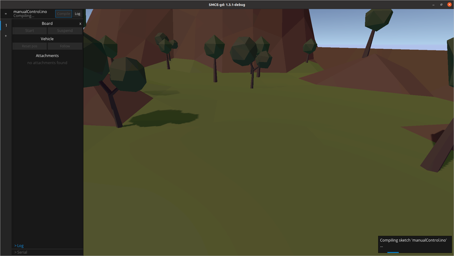
When the compilation is successfully finished, click on the Start button.
You will see the car popping up in the virtual world. Cool right? Let’s drive it!
Click on the Serial option on the bottom left of the screen, type f and press “Enter” on your keyboard.
The car will start driving. Press the Follow option to make the camera move along with the car and play
around with the simple commands we described above. When you are done, you can click on Stop.
Pro-tip: You may want to put a tiny delay at the end of your loop() function (e.g. delay(1)) just so
to avoid straining your CPU resources, since the emulator will be looping really fast through your sketch.
Using the sensors
Now that you have a sense of how the environment physics and how to send commands via the serial port to the
car, let’s use some sensors to have the car move autonomously.
By default the car comes pre-loaded
with a bunch of handy sensors. The default configuration includes an ultrasound sensor
(SR04) on the front of
the vehicle, connected to pins 6 and 7. Let’s use the sensor to stop the car if there’s an obstacle closer than
70 centimeters.
#include <Smartcar.h>

ArduinoRuntime arduinoRuntime;
BrushedMotor leftMotor{arduinoRuntime, smartcarlib::pins::v2::leftMotorPins};
BrushedMotor rightMotor{arduinoRuntime, smartcarlib::pins::v2::rightMotorPins};
DifferentialControl control{leftMotor, rightMotor};

SimpleCar car(control);

const int triggerPin           = 6; // D6
const int echoPin              = 7; // D7
const unsigned int maxDistance = 100;
SR04 front{arduinoRuntime, triggerPin, echoPin, maxDistance};

void setup()
{
  // Move the car with 50% of its full speed
  car.setSpeed(50);
}

void loop()
{
  const auto distance = front.getDistance();
  // When distance is `0` it means there's no obstacle detected
  if (distance > 0 && distance < 70) {
    car.setSpeed(0);
  }

#ifdef __SMCE__
  // Avoid over-using the CPU if we are running in the emulator
  delay(1);
#endif
}
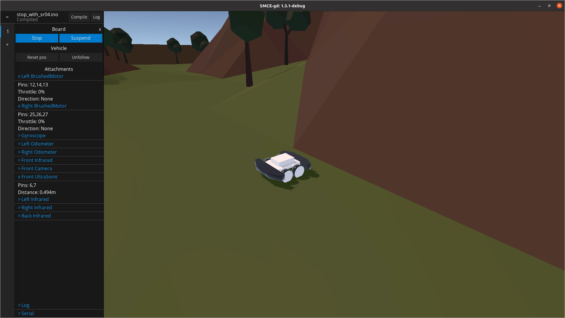
Load up the sketch and run it in the emulator. It will keep driving straight until it meets an obstacle.
You can monitor the sensor readings in real time by clicking on them on the left side of the screen.
In the screenshot below, we can see that once the wall is met, no throttle is supplied to the motors and the
detected distance is within the expected range.
Pro-tip: If you press F3 you will get an indication of where the sensors are pointed to, as well as
their range. This is particularly valuable for debugging the sensor input.
As an extra layer of realism, the sensor readings are purposefully not completely accurate and contain noisy. The sensors currently available in the default setup are:
- One SR04 ultrasonic sensor on the front of the vehicle that has relatively long range, however, its measurements are rather slow and noisy.
- Four SHARP infrared sensors (e.g. GP2Y0A21), on the sides of the car. Their range is shorter but are more accurate and fast.
- Two directional odometers, one on each side, that measure how much the car has traveled.
- One GY50 gyroscope that can tell you the car’s orientation or, rather, angular displacement in degrees [0, 360).
- An OV767X camera that can be used to stream what the car sees.
Connectivity
Sending commands via the serial port and making the car move autonomously based on the sensor input is fun, but there’s
an undeniable limit to what you can accomplish. You often need your vehicle to communicate with the “outside world” whether that may be
an app on a different device or a server.
The physical Smartcar platform is built around an ESP32
microcontroller, so it can easily connect to other devices via WiFi or Bluetooth.
SMCE allows its users to emulate connectivity via WiFi and MQTT.
While the emulation of the WiFi library is not entirely there yet since there’s still work to be done, it shouldn’t take more
than some #ifdef __SMCE__ to write an Arduino sketch that seamlessly works on both the real hardware and the emulator.
Let’s see how you can write a simple sketch that controls the car via MQTT messages and broadcasts telemetry data, i.e. the
distance measurements of the front ultrasound sensor.
Note: While the following sketch works fine on SMCE, it needs a few additions/changes to run on an actual ESP32,
mainly in regards to the WiFi connection.
#include <MQTT.h>
#include <WiFi.h>

#include <Smartcar.h>

#ifndef __SMCE__
WiFiClient net;
#endif
MQTTClient mqtt;

ArduinoRuntime arduinoRuntime;
BrushedMotor leftMotor(arduinoRuntime, smartcarlib::pins::v2::leftMotorPins);
BrushedMotor rightMotor(arduinoRuntime, smartcarlib::pins::v2::rightMotorPins);
DifferentialControl control(leftMotor, rightMotor);

SimpleCar car(control);

const auto oneSecond = 1000UL;
const auto triggerPin = 6;
const auto echoPin = 7;
const auto maxDistance = 400;
SR04 front(arduinoRuntime, triggerPin, echoPin, maxDistance);

void setup() {
  Serial.begin(9600);
#ifdef __SMCE__
  // ================= 1
  // mqtt.begin("aerostun.dev", 1883, WiFi);
  mqtt.begin(WiFi); // Will connect to localhost
#else
  mqtt.begin(net);
#endif
  // ================= 2
  if (mqtt.connect("arduino", "public", "public")) {
    mqtt.subscribe("/smartcar/control/#", 1);
    mqtt.onMessage([](String topic, String message) {
      if (topic == "/smartcar/control/throttle") {
        car.setSpeed(message.toInt());
      } else if (topic == "/smartcar/control/steering") {
        car.setAngle(message.toInt());
      } else {
        Serial.println(topic + " " + message);
      }
    });
  }
}

void loop() {
  if (mqtt.connected()) {
    mqtt.loop();
    const auto currentTime = millis();
    static auto previousTransmission = 0UL;
    if (currentTime - previousTransmission >= oneSecond) {
      previousTransmission = currentTime;
      const auto distance = String(front.getDistance());
      // ================= 3
      mqtt.publish("/smartcar/ultrasound/front", distance);
    }
  }
#ifdef __SMCE__
  // Avoid over-using the CPU if we are running in the emulator
  delay(1);
#endif
}
There are three interesting points in the sketch that I have highlighted with an inline comment followed by =================:
- This is where the connection to the MQTT broker is established. If no arguments are passed to
beginthen it will connect tolocalhost. It is your responsibility to set up the broker either locally or at a remote host. - Here we subscribe to the topics we are interested in and define what shall happen once a message with the particular topic is received.
- We want to provide some feedback, so we send/publish the distance measured by the front-looking ultrasound sensor, every one second.
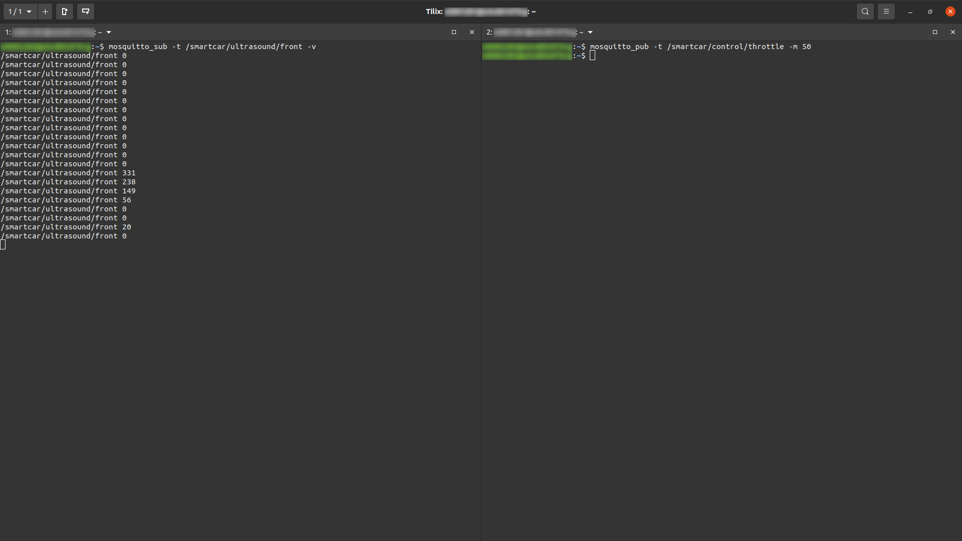
If you are on Ubuntu, Mosquitto is one of the easiest MQTT brokers to set up. I used the mosquitto_pub
and mosquitto_sub utilities to subscribe to the front ultrasonic sensor measurements and send throttle commands as you can see
in the screenshot below.
The car started moving with speed 50 once it got the appropriate message at the /smartcar/control/throttle topic and kept
broadcasting the measured distance at /smartcar/ultrasound/front.
Camera
When trying to make sense of your rover’s environment, the sensors will only get you so far.
SMCE allows you to get an image stream of the virtual world. This way, you can either do some very simple image-processing on
the car’s microcontroller itself or broadcast the image stream to a more capable device and do the image processing there.
For simplicity, only the Arduino_OV767X library is supported by SMCE
and MQTT can be utilized to broadcast the stream.
Let’s take a look at a sketch that provides an image stream for MQTT clients listening to /smartcar/camera. It is the same as
before, with the addition of the camera stream:
#include <vector>

#include <MQTT.h>
#include <WiFi.h>
#include <OV767X.h>

#include <Smartcar.h>

#ifndef __SMCE__
WiFiClient net;
#endif
MQTTClient mqtt;

ArduinoRuntime arduinoRuntime;
BrushedMotor leftMotor(arduinoRuntime, smartcarlib::pins::v2::leftMotorPins);
BrushedMotor rightMotor(arduinoRuntime, smartcarlib::pins::v2::rightMotorPins);
DifferentialControl control(leftMotor, rightMotor);

SimpleCar car(control);

const auto oneSecond = 1000UL;
const auto triggerPin = 6;
const auto echoPin = 7;
const auto maxDistance = 400;
SR04 front(arduinoRuntime, triggerPin, echoPin, maxDistance);

std::vector<char> frameBuffer;

void setup() {
  Serial.begin(9600);
  Camera.begin(QVGA, RGB888, 15);
  // ================= 1
  frameBuffer.resize(Camera.width() * Camera.height() * Camera.bytesPerPixel());
#ifdef __SMCE__
  // mqtt.begin("aerostun.dev", 1883, WiFi);
  mqtt.begin(WiFi); // Will connect to localhost
#else
  mqtt.begin(net);
#endif
  if (mqtt.connect("arduino", "public", "public")) {
    mqtt.subscribe("/smartcar/control/#", 1);
    mqtt.onMessage([](String topic, String message) {
      if (topic == "/smartcar/control/throttle") {
        car.setSpeed(message.toInt());
      } else if (topic == "/smartcar/control/steering") {
        car.setAngle(message.toInt());
      } else {
        Serial.println(topic + " " + message);
      }
    });
  }
}

void loop() {
  if (mqtt.connected()) {
    mqtt.loop();
    const auto currentTime = millis();
    static auto previousFrame = 0UL;
    // ================= 2
    if (currentTime - previousFrame >= 65) {
      previousFrame = currentTime;
      Camera.readFrame(frameBuffer.data());
      mqtt.publish("/smartcar/camera", frameBuffer.data(), frameBuffer.size(),
                   false, 0);
    }
    static auto previousTransmission = 0UL;
    if (currentTime - previousTransmission >= oneSecond) {
      previousTransmission = currentTime;
      const auto distance = String(front.getDistance());
      mqtt.publish("/smartcar/ultrasound/front", distance);
    }
  }
#ifdef __SMCE__
  // Avoid over-using the CPU if we are running in the emulator
  delay(1);
#endif
}
- Allocate adequate memory on the heap to contain a single frame.
- Every
65milliseconds, read a frame from the camera and copy it insideframeBuffer. Then broadcast it via MQTT.
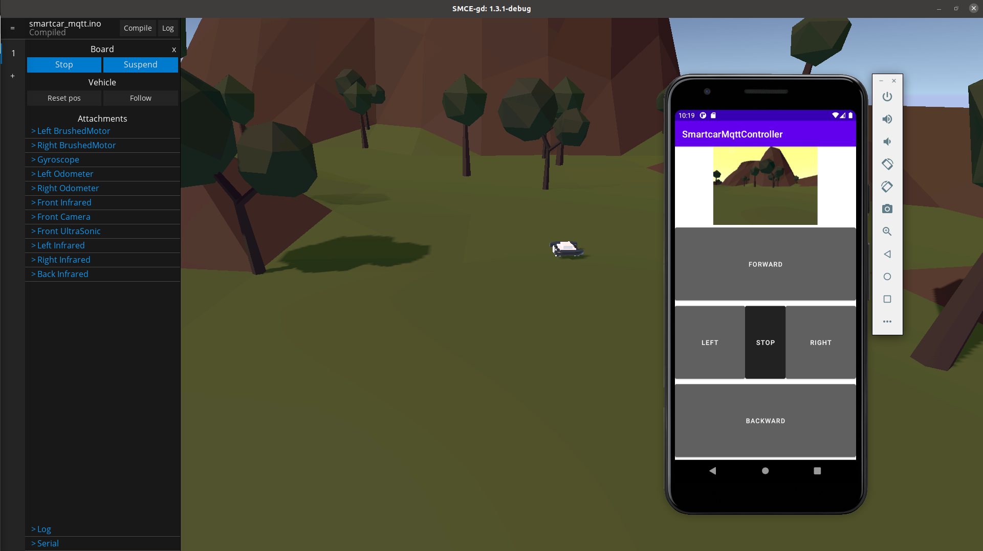
To show you what this could look like with a real scenario, there is a reference Android app that you can use to control the car via MQTT messages as well as visualize the stream of images. It is not the prettiest, but you will get the gist of how things are done with JAVA and Android.
Custom sensor configuration
By default, the vehicle comes preloaded with a specific set of sensors, actuators and pins available. This is described in SMCE’s wiki, under
Vehicle Capabilities.
To use your own setup, you can define your custom configuration, using json files placed in the same directory as your sketch.
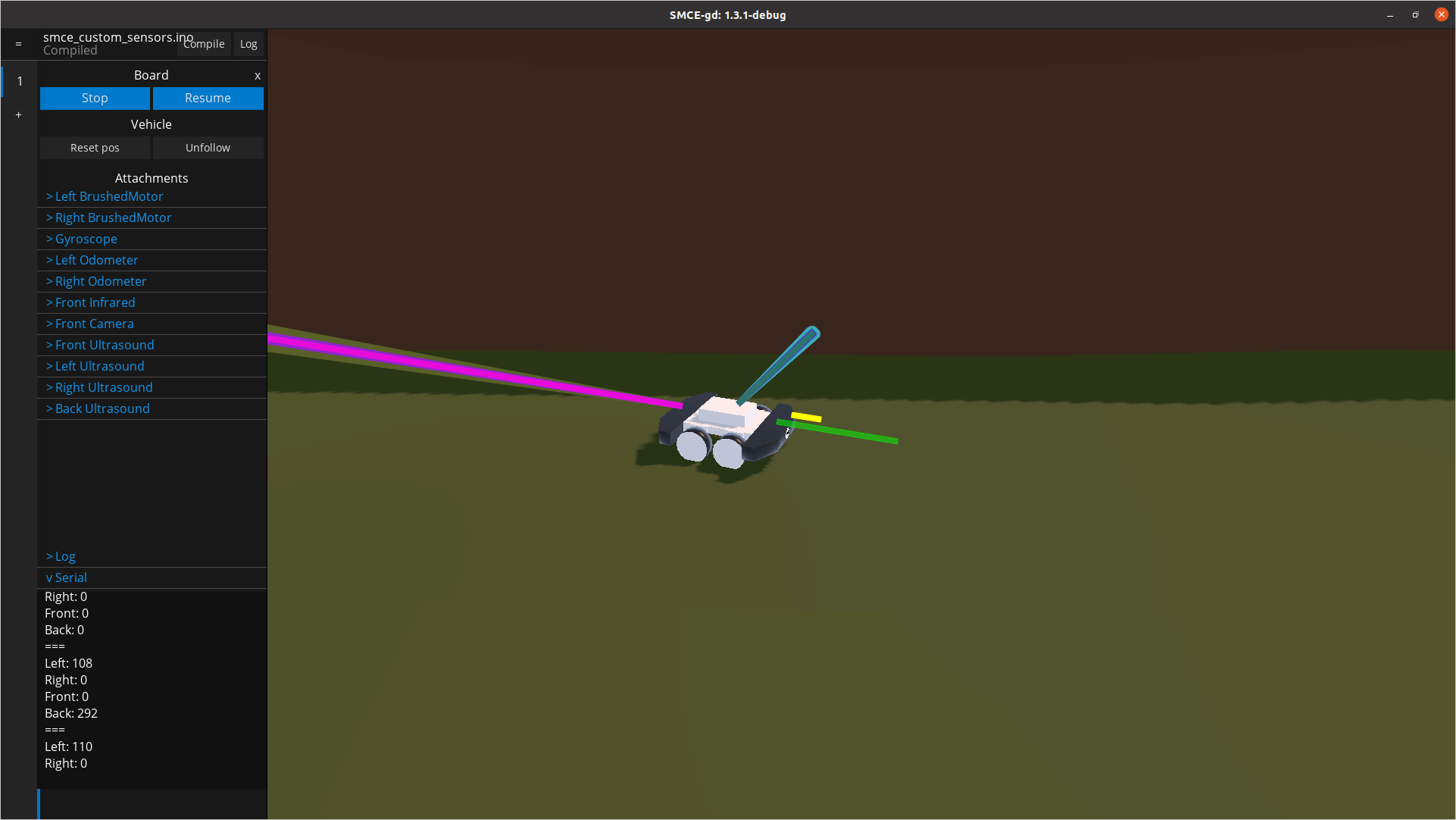
Let’s assume we would like to have a sketch that allows us to drive the car via the serial port (as demonstrated previously),
take measurement distances from all four sides of the vehicle and send them to us. You would end up with a sketch like the one below:
#include <Smartcar.h>

const int fSpeed   = 70;  // 70% of the full speed forward
const int bSpeed   = -70; // 70% of the full speed backward
const int lDegrees = -75; // degrees to turn left
const int rDegrees = 75;  // degrees to turn right
const unsigned long transmissionInterval = 100; // In milliseconds
const int maxDistance = 300;

ArduinoRuntime arduinoRuntime;
BrushedMotor leftMotor(arduinoRuntime, smartcarlib::pins::v2::leftMotorPins);
BrushedMotor rightMotor(arduinoRuntime, smartcarlib::pins::v2::rightMotorPins);
DifferentialControl control(leftMotor, rightMotor);

SimpleCar car(control);

// ================= 1
SR04 left(arduinoRuntime, 2, 3, maxDistance); // trigger and echo pin respectively
SR04 right(arduinoRuntime, 4, 5, maxDistance);
SR04 front(arduinoRuntime, 6, 7, maxDistance);
SR04 back(arduinoRuntime, 16, 17, maxDistance);

void setup()
{
  Serial.begin(9600);
}

void loop()
{
  static auto previousTransmission = 0UL;
  const auto currentTime = millis();
  // ================= 2
  if (currentTime > previousTransmission + transmissionInterval) {
    previousTransmission = currentTime;
    Serial.println("===");
    Serial.println("Left: " + String(left.getDistance()));
    Serial.println("Right: " + String(right.getDistance()));
    Serial.println("Front: " + String(front.getDistance()));
    Serial.println("Back: " + String(back.getDistance()));
  }

  handleInput();
#ifdef __SMCE__
  // Avoid over-using the CPU if we are running in the emulator
  delay(1);
#endif
}

void handleInput()
{
  if (Serial.available())
  {
    char input = Serial.read(); // read everything that has been received so far and log down
    // the last entry
    switch (input)
    {
      case 'l': // rotate counter-clockwise going forward
        car.setSpeed(fSpeed);
        car.setAngle(lDegrees);
        break;
      case 'r': // turn clock-wise
        car.setSpeed(fSpeed);
        car.setAngle(rDegrees);
        break;
      case 'f': // go ahead
        car.setSpeed(fSpeed);
        car.setAngle(0);
        break;
      case 'b': // go back
        car.setSpeed(bSpeed);
        car.setAngle(0);
        break;
      default: // if you receive something that you don't know, just stop
        car.setSpeed(0);
        car.setAngle(0);
    }
  }
}
- Here we define the pins our sensor should be attached to. For example, the
leftultrasound (SR04) sensor is attached to pins2and3. The former is the trigger pin and the latter is the echo pin. - We “print” out the measurements via the serial port, at the interval specified by the value of
transmissionInterval.
The default setup does not support the sketch above because of two reasons: (a) the default car is not equipped with four SR04
sensors but just one and, (b) pins 16 and 17 that are available on a typical ESP32 board are not available on the default emulated
board. Fortunately we can change that!
The first thing we need to do is make all necessary pins available and ensure they are of the correct type (i.e. digital or analog).
Here we should note that due to technicalities, the echo pin of the SR04 sensor must be specified as analog. Here are the steps
you should follow:
- Create an empty
board_config.jsonfile in the same directory as your sketch. - Get the default board configuration used by SMCE, so we can build upon (patch) it.
- Use the
gpio_driversattribute to specify all pins that your sketch would require. Note: Don’t forget you will need to specify the pins necessary for the motors, the odometers (if you use them), the gyroscope etc. In my case, I wanted to remove some pins (0and1) that I do not use, add the new ones (16and17) and make sure that all pins used by theSR04sensors are in the correct mode.
{
    "gpio_drivers": [
        { "pin": 2, "digital": true },
        { "pin": 3, "analog": true },
        { "pin": 4, "digital": true },
        { "pin": 5, "analog": true },
        { "pin": 6, "digital": true },
        { "pin": 7, "analog": true },
        { "pin": 16, "digital": true },
        { "pin": 17, "analog": true },

        { "pin": 12, "digital": true },
        { "pin": 13, "analog": true },
        { "pin": 14, "digital": true },

        { "pin": 18, "analog": true },

        { "pin": 25, "digital": true },
        { "pin": 26, "digital": true },
        { "pin": 27, "analog": true },

        { "pin": 34, "digital": true },
        { "pin": 35, "analog": true },
        { "pin": 85, "analog": true },
        { "pin": 135, "analog": true },

        { "pin": 39, "digital": true },
        { "pin": 36, "analog": true },
        { "pin": 86, "analog": true },
        { "pin": 136, "analog": true },

        { "pin": 250, "digital": true },

        { "pin": 205, "analog": true }
    ]
}
After you have created your board_config.json file which specifies which pins are available on the emulated Arduino board, time to
set up your vehicle. Similarly, we will use the default setup for inspiration and patch it accordingly.
- Create a
vehicle_config.jsonfile in the same directory as your sketch. - Get the default vehicle configuration used by SMCE so we can build upon it.
- Change the
slotsthat you are interested in. In my case, I wanted to attachSR04sensors at theLeft,RightandBackslots, using the same pins as the ones in my sketch and making sure that those pins have already been made available by theboard_config.json.
{
   "slots": {
      "Left": {
         "class": "UltraSonic",
         "name": "Left Ultrasound",
         "props": {
            "trigger_pin": 2,
            "echo_pin": 3
         }
      },
      "Right": {
         "class": "UltraSonic",
         "name": "Right Ultrasound",
         "props": {
            "trigger_pin": 4,
            "echo_pin": 5
         }
      },
      "FrontTop": {
         "class": "UltraSonic",
         "name": "Front Ultrasound",
         "props": {
            "trigger_pin": 6,
            "echo_pin": 7
         }
      },
      "Back": {
         "class": "UltraSonic",
         "name": "Back Ultrasound",
         "props": {
            "trigger_pin": 16,
            "echo_pin": 17
         }
      }
   }
}
Pro-tip: If you want to completely overwrite any of the configurations, you can add set the from_scratch top-level element to true.
This can be useful if you would like to completely remove the camera or other sensors occupying slots that you are not using at all.
The same goes for pins. For example, the configuration found below would create a car equipped with just a single ultrasound sensor on its rear side
and a pair of motors. Nothing else, no cameras, no odometers, no gyroscope.
{
   "from_scratch": true,
   "vehicle": "RayCar",
   "slots": {
      "Back": {
         "class": "UltraSonic",
         "name": "Back Ultrasound",
         "props": {
            "trigger_pin": 16,
            "echo_pin": 17
         }
      }
   },
   "builtin": {
      "Left BrushedMotor": {
         "forward_pin": 12,
         "backward_pin": 14,
         "enable_pin": 13
      },
      "Right BrushedMotor": {
         "forward_pin": 25,
         "backward_pin": 26,
         "enable_pin": 27
      }
   }
}
Modding the environment
If you find yourself limited by the default virtual world, you have the opportunity to create mods and build your own
fascinating 3D environment for your car to roam in.
I am not very well-versed on the particular topic and since elaborating more on it would make this long article even more extensive,
I will refer you to SMCE’s official modding guidelines.
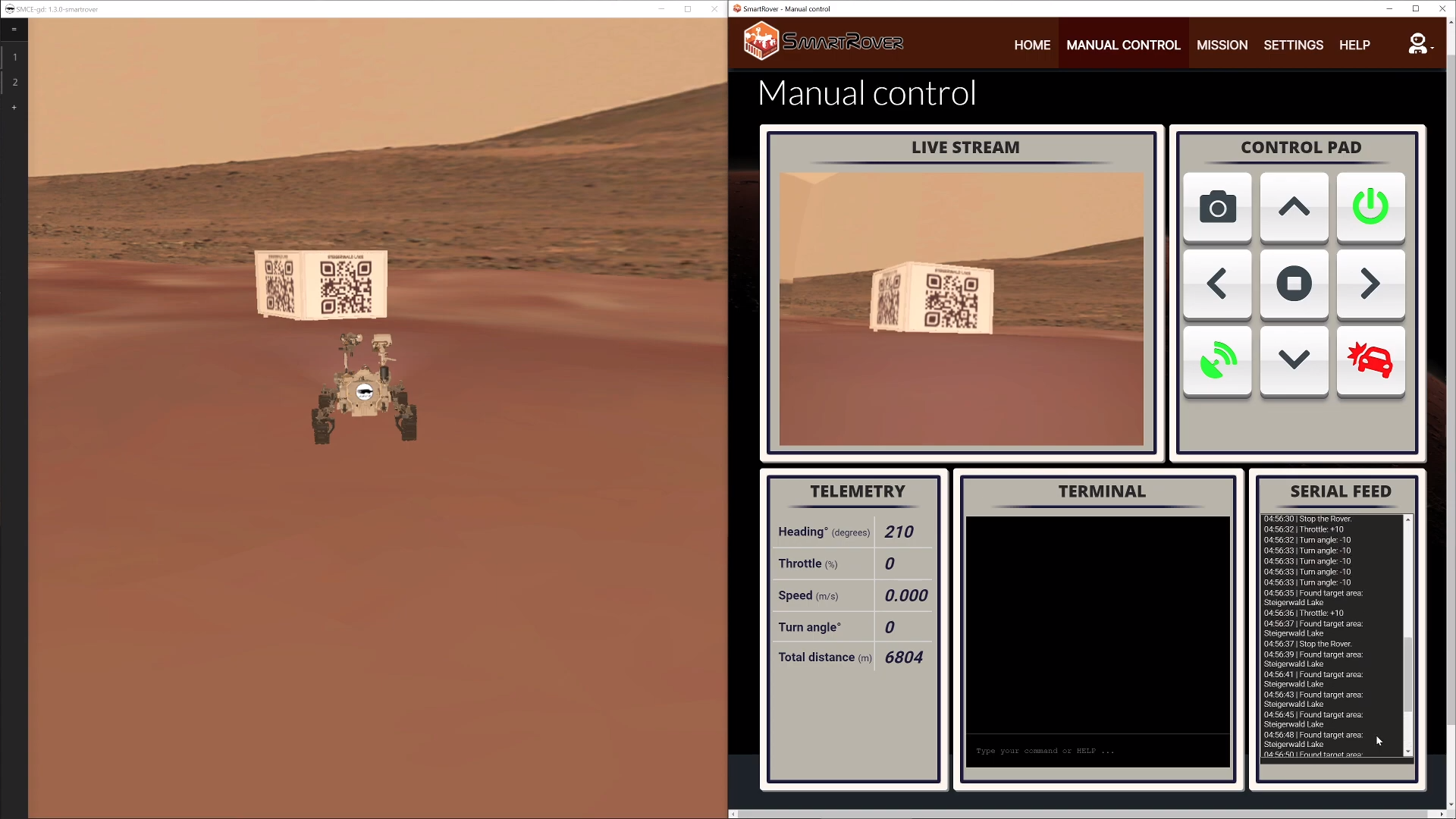
Last spring, some very talented 1st year BSc software engineering students created a Mars rover mod for SMCE.
They run their emulated vehicle… on a different planet!
You should definitely check out their incredible project on GitHub and watch their demo video:
