ATtiny85 line following truck
20 April 2015
I am organizing a workshop on ATtiny85 programming this week, so I built a model truck that can either be remotely controlled or tasked to follow a line! Read on for the story behind it, schematics, photos and videos.
Recently, I was at a big toy store (Jumbo), looking for a gift for a 5 year old boy, when I spotted some really cheap (4€) vehicle construction kits. They were Meccano knock-offs, which I used to have as a kid and to be honest, did not like them much back then. Nonetheless, I immediately saw the potential and thought it should not be too hard to hack one of them and turn it into a remote controllable vehicle. There were four options: a race car, a crane, a tank and a truck. I favored the latter, due to the fact that it provided a lot of free space in its trunk and relative freedom to modify it.

The main reason behind this, is that I am organizing a workshop on ATtiny85 programming this week, so I would like to show off an additional application with the particular microcontroller, apart of the killswitch and the interactive name tag. Hopefully, some might get inspired this way!
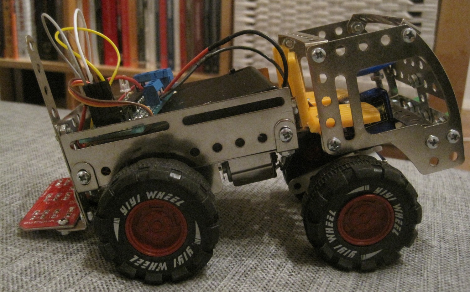
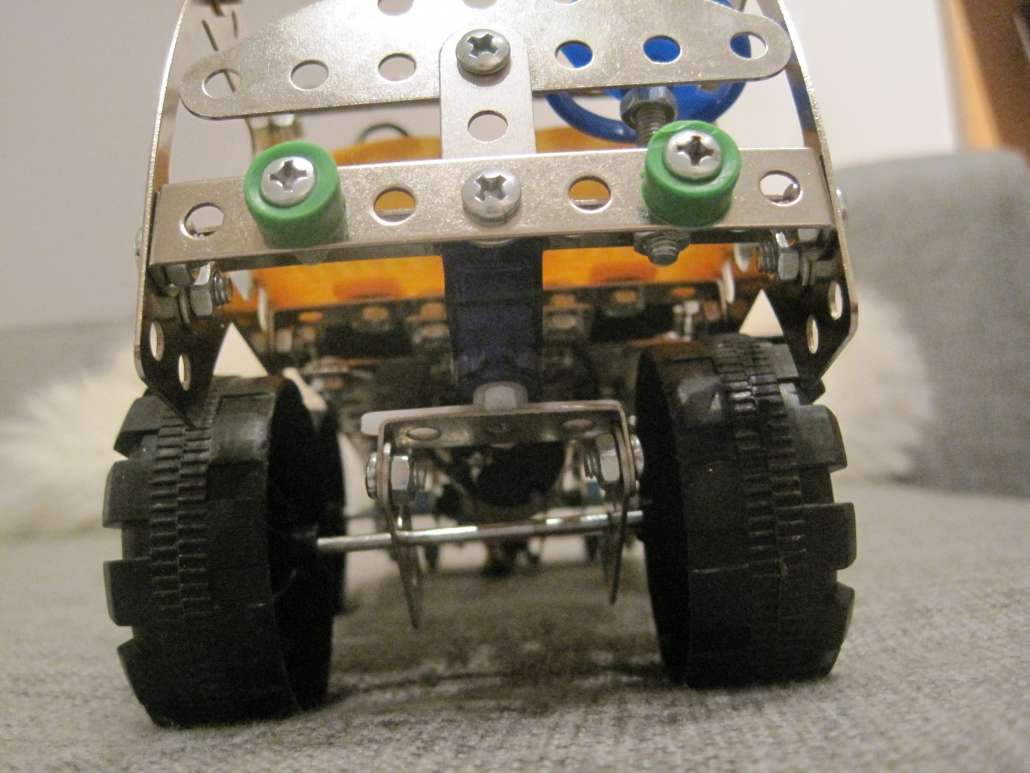
The first challenge I encountered was that the default construction did not predict steering and motors. The wheels were attached to two axis, so the truck could be just pushed back and forth. Initially I considered using two motors, in order to rotate the car. However, that would be uglier and much harder to put together, due to the lack of space and resources (the little metal pieces were running out!). The alternative was to use one motor and one steering wheel.
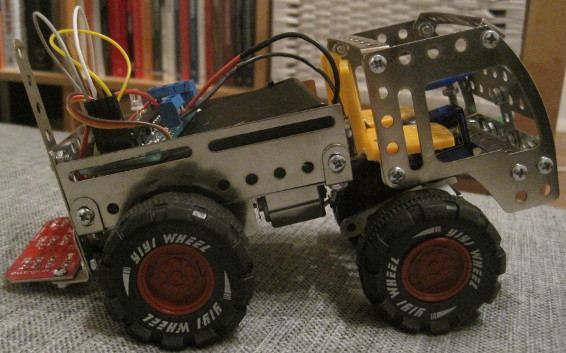
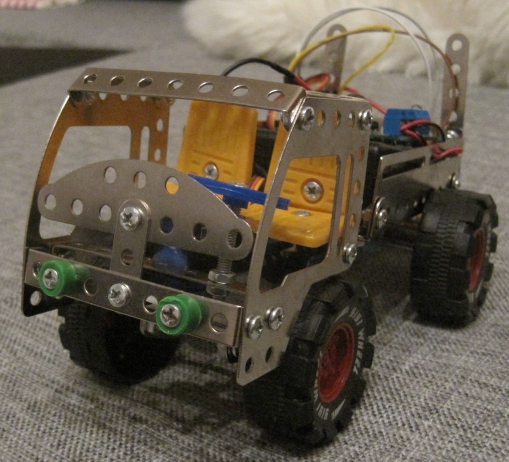
I bought a gear box from a local shop, attached it to the already existing chassis and glued a servo to create a steering wheel. Unfortunately, I ran out of pieces, so the front wheels are closer to the ground than the rear ones.
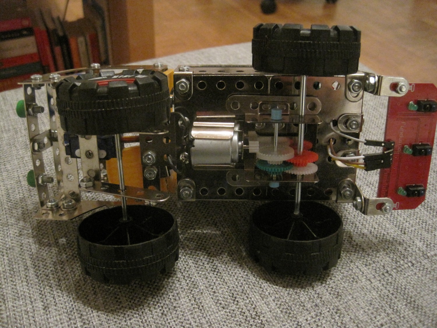
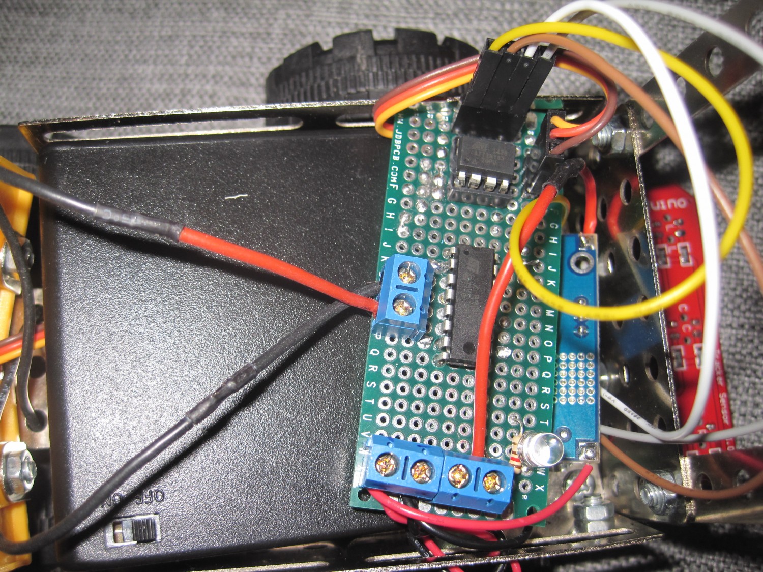
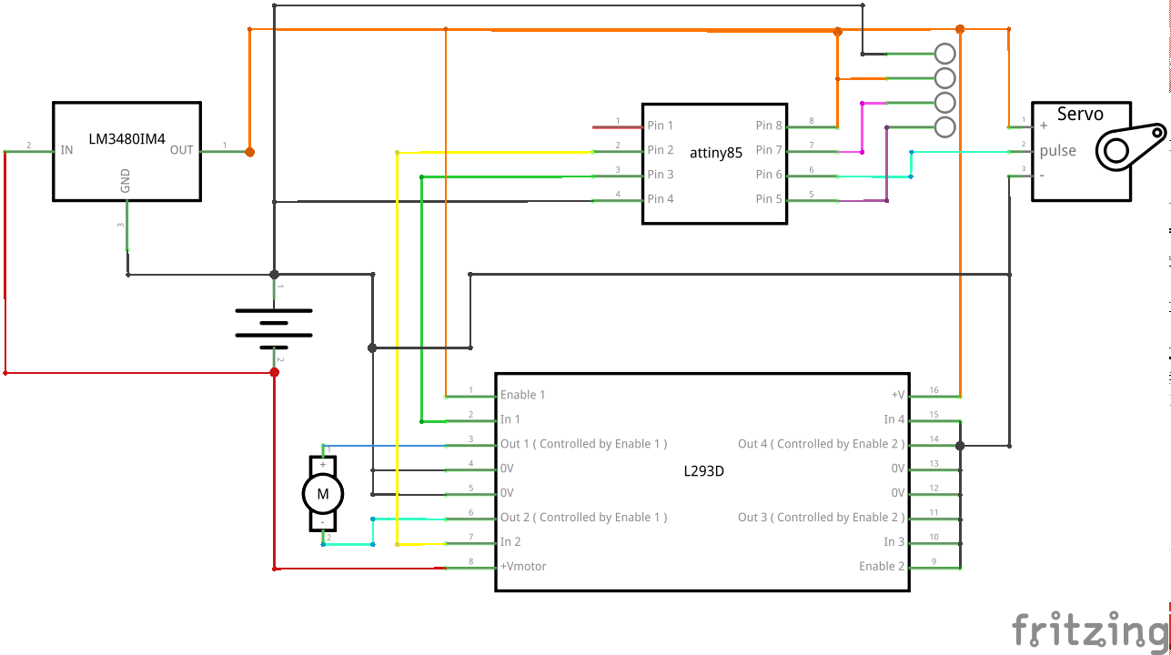
In order to drive the motor, I used one of the L293D dual half-bridge chips I purchased some months ago, but never used. To my great frustration, this chip drops down the supplied voltage and generally does not cope well with low voltages. So despite the fact that the motor could be driven with 3 Volts, the L293D needs at least 5 Volts, to operate properly. This meant, my initial plans to install 3 AAA batteries in order to power up everything, ended up in the trash bin and a 4 AA battery pack was placed instead. Unfortunately, 4 AA batteries meant that I could not hook them up straight to the ATtiny85 whose maximum input voltage is 5.5 Volts. I know I should not have, but I actually tried to power it up with 6 Volts anyway, hoping it would work. Ιts behavior would become very unpredictable, so do not try it. To solve this, I used a LM2596 based voltage regulator. Finally everything, Bluetooth, DC motor and the Servo, worked properly.
Check out a video of a friend of mine driving the truck using his android phone. It specifically receives the same commands as the bluetooth controlled spider.
I purposefully left two specific ATtiny85 pins unused and connected them to female headers so they are easily accessible. They can be connected to a Bluetooth module, other sensors or even I2C devices! If you want to learn how this feature proved particularly useful, keep reading, but first check the schematics out.
After showing my new gadget to some friends, I started to get the feeling that “I have done this before”, which is not quite true, since it was the first time I created a steering wheel from scratch, used a gearbox and worked with a bare bones L293D. But still, the thought was there. I am involved in a university project where we are working on an autonomous car which can follow street lanes, so I said to myself “why not line following?”.
At first I got excited and thought of trying some PID control algorithms, to follow a line smoothly, however the fact that I had just two available pins on the microcontroller, crossed that option out. I used a three infra red array I bought last summer and mounted it neatly on the back of the truck. I had to make sure it was close enough to the ground, but the final result looks decent.
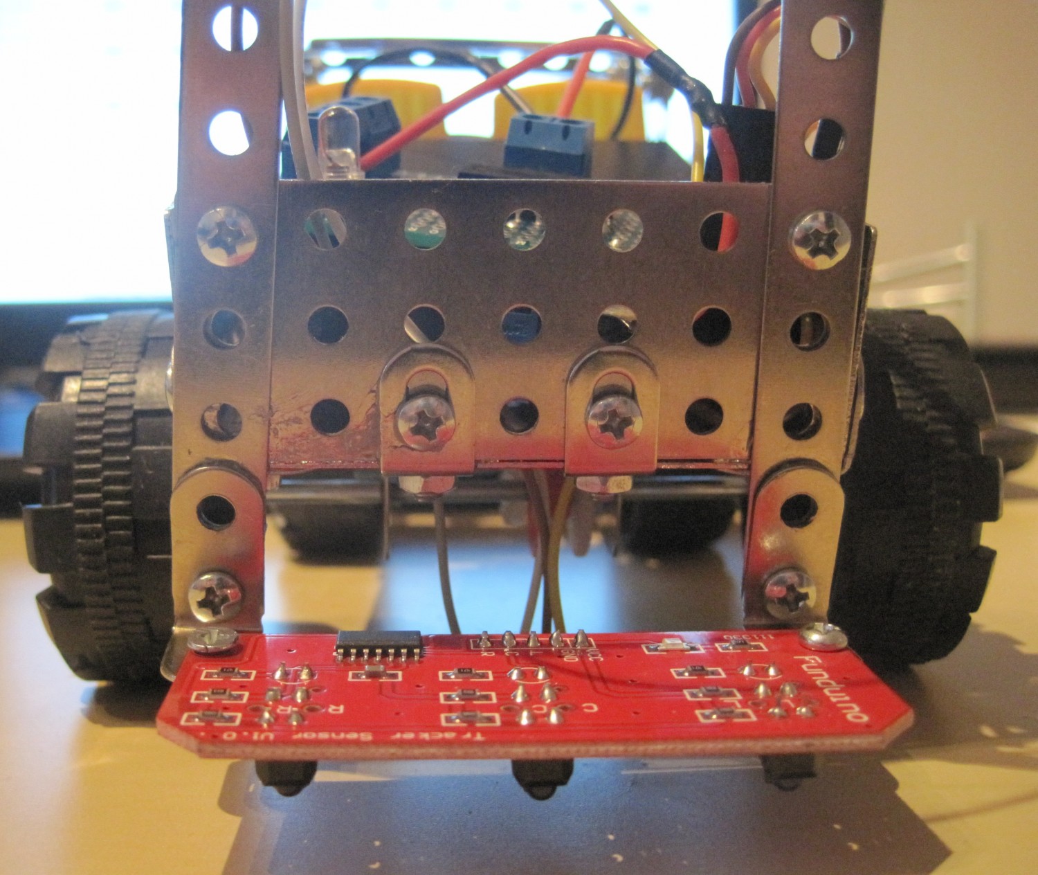
The approach to line following is pretty straight forward: if the right side infra red starts “seeing” the line, then the truck is commanded to turn right, until the infra reds stop sensing the line (in other words, the line is between the two sensors). Similarly for the left side. Unfortunately, due to the fact that the servo is not strong to turn fast enough, the truck easily loses the line if it is either too thin or has a steep turn. Below you can view two line following examples. In the curved line video, the lights are on, but strangely enough what the camera recorded, turned out really dark.
To switch between with two modes, line following or manual, one must simply plug in the equivalent component (infrared array or Bluetooth module) and change one variable in the code.
To conclude, it was a fruitful learning experience and a very fun project overall, that demonstrates some of the capabilities of ATtiny85.